This post is older than 2 years and might not be relevant anymore
More Info: Consider searching for newer posts

Programming different nRF51822 boards

Hi, student here, so go easy if you can :)

I have successfully programmed the evaluation kit and development with the softdevice and loaded my app on.

Now I am trying to work with some boards that I ordered online. One is a breakout board http://gd1.alicdn.com/bao/uploaded/i1/10051019304971428/T1RU.hXeXiXXXXXXXX_!!0-item_pic.jpg_460x460.jpg http://s30.postimg.org/9a59uguv3/nrf51822.png

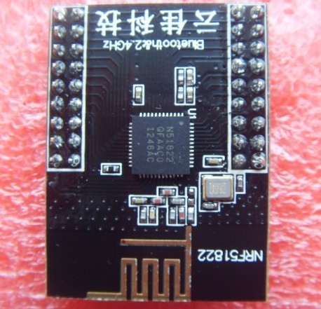
and other is a 3rd party bluetooth module listed here www.nordicsemi.com/.../3rd-Party-Bluetooth-low-energy-Modules The module I am using is the PTR5518

I have the J-LINK LITE CortexM and the J Link Edu.

I am not sure where to start to program those two boards. Where do I start ?

Thank you!

  • FormerMember
    0 FormerMember in reply to David

    Yes, he can copy the example codes to the custom made board. The chips are the same in both cases, the difference between the development kit and the custom made board is what is connected to the I/Os (pins) on the nRF51822 chip.

  • John,

    I am using a PTR5518 as well as a J-Link Edu here.

    I don't know if you resolved your pinout issue, but here is how I did it:

    • PTR5518 pin 7 to ground.
    • PTR5518 pin 10 to Vcc (3.3 V in my case)
    • PTR5518 pin 4 to JTAG pin 7 (SWDIO)
    • PTR5518 pin 5 to JTAG pin 9 (SWCLK)
    • JTAG pin 1 to the same Vcc
    • JTAG pin 4 to ground

    As for the headers & SDK, I found that you can generally use them, but some changes are needed here and there. The board obviously has no LEDs or buttons on its own, so you must be mindful of that (and I don't believe it exposes the same pins as the LEDs on the eval board). The board has a 250 ppm external crystal rather than a 25 ppm one, and so you must account for this in the SOFTDEVICE_HANDLER_INIT call (it seems to be the same problem documented here). I had modified my code to use something like what was here:

    
        NRF_CLOCK->XTALFREQ = 0;
        NRF_CLOCK->EVENTS_HFCLKSTARTED = 0;
        NRF_CLOCK->TASKS_HFCLKSTART = 1;
        while (NRF_CLOCK->EVENTS_HFCLKSTARTED == 0);
        SOFTDEVICE_HANDLER_INIT(NRF_CLOCK_LFCLKSRC_RC_250_PPM_4000MS_CALIBRATION, false);


    to replace SOFTDEVICE_HANDLER_INIT(NRF_CLOCK_LFCLKSRC_XTAL_20_PPM, false);

    (It seems like I should be able to just switch that line to use NRF_CLOCK_LFCLKSRC_XTAL_250_PPM instead but for some reason this does not work , nor does the 500 ppm setting.)

    Finally, a question for you: What is the breakout board you show in the photo?

  • Chris, thanks for the detailed explanation. I'm just starting to get the pin outs figure out. Do you have photo of your setup by any chance ? Did you solder header pins on to PTR5518 directly ? Curious to see how you are going about it.

    I ordered the board from here www.ebay.com/.../121113398808

  • Thank you for that link.

    As for my own setup, I soldered a series of thin wires to each contact, routed them through the holes in some perfboard, soldered the other side to a header, and hot-glued everything in place. It's very ugly, but it works and it's secure.

    However, it was enough work that the module you linked to is probably preferable (plus it has all the GPIOs, it looks like).

  • I used the pin 6 and 7 for the BLE_Health thermometer with NRF Break Out Board. how do you do pin assignment? state 20 and 22.

    Thanks

Related