
Hi,
i'm designing a board based on NRF51822-QFAC chip and i'm using this antenna chip 2450AT43A100E and this balun 2450BM14E0003T .
I put the balun as close as possible to the NRF51822 and i choose the width track to be equal to 50 ohm using the Coplanar waveguide calculator.
above is a preview of the antenna / balun ....
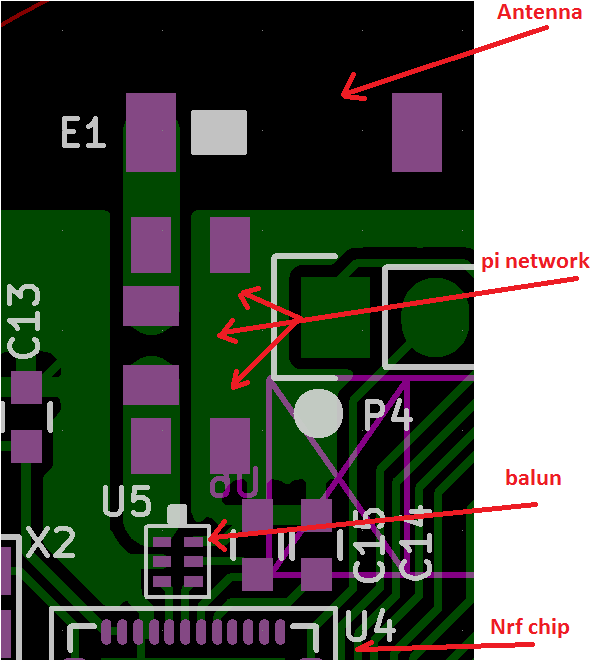
and i'm planing to tune the antenna after the board will be assembled.
my questions are :
1/ can i get the maximum range that the BLE can have with this design ? is the antenna tuning ,that alows us to determine the pi network values, is enough to get the maximum range ?
should i make any hardware change ? like changing the antenna for a better one ?
2/ is there any software modification that i can make to enhance the antenna signal power ? i remember reading some member here talking about changing the signal power of the nrf.
3/ i'm planing to hand soldering the board and then tune the antenna to determine the PI network values. is that OK ? i mean the hand soldering won't be different from the pick and place machine and hence getting a false pi network values when making the final product ? let's suppose that the hand soldering are made by a professional and are well done.
4/ the board will be putted inside a case. the case is aluminum in the TOP where the antenna will be placed and plastic in the bottom side. did the aluminum case affect the signal strength ?
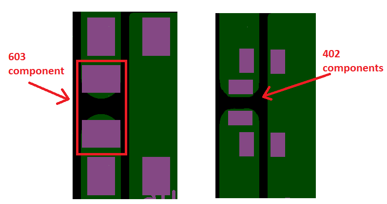
5/ for the pi network i choose a 603 component size because the 603 width component match with the 50 Ohm trace width of the antenna that i calculated (see image above).
so i'm worrying if i choose a 402 component they will be too small compared to the trace width. is that correct ? can i use a 402 component without any issue ?
Thanks,
