This post is older than 2 years and might not be relevant anymore
More Info: Consider searching for newer posts

SPI MOSI default high? NRF SDK 12.2.0

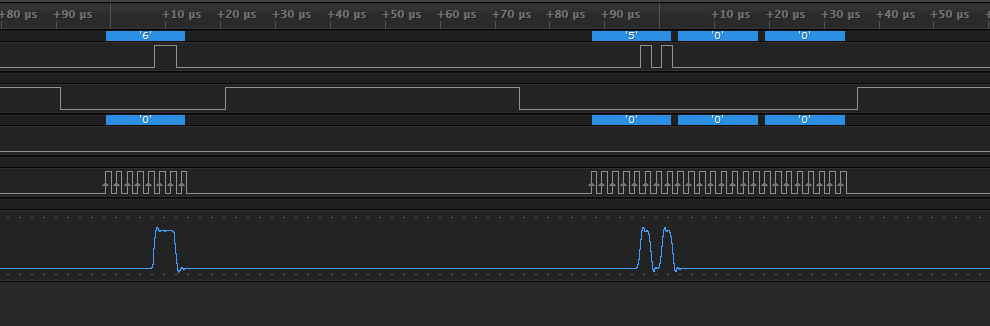
I am attempting to interface a Winbond flash device with the NRF52. The datasheet does not specify the idle state of MOSI when reading from the device. However, I cannot make the flash chip work with the NRF52. In the attached image, an Arduino successfully sends a command to the devices (0x06H) then reads a register (0x05H) and gets the expected result (0x02H).

Arduino

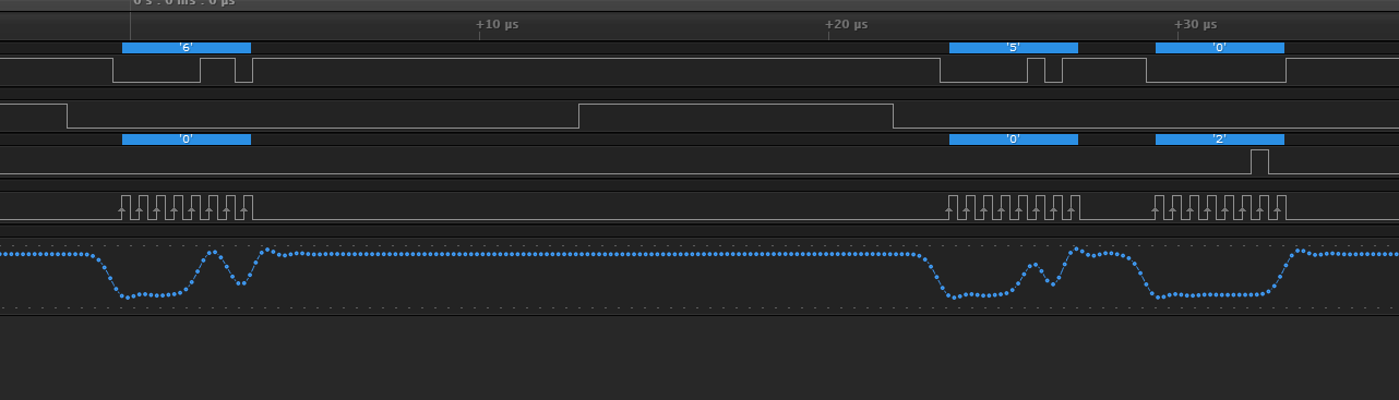
As you can see here, a NRF52 sending the same sequence of commands (roughly speaking) does not get a response. I've tried a number of different frequencies and both mode 0 and 3, which are the two modes the flash chip supports.

NRF52 on BMD-300 eval

The one obvious difference between the Arduino's output and the NRF52's output is the state of MOSI in between transfers. Although the flash memory specifies a D/C during idle periods I would like to try setting MOSI high during idle periods.

Is there a way to do this?

Parents
  • Unfortunately setting the MOSI pin high will not change the pins polarity between transmissions. The SPI hardware takes control of the pin, and it will keep the pin low between transmissions. After the SPI is uninitialized the pin will maintain its configuration (low) until the application changes this. The only way I can think of to achieve a high MOSI pin between transmissions is to unititialize the SPI between every transmission and "manually" set the pin high.

Reply
  • Unfortunately setting the MOSI pin high will not change the pins polarity between transmissions. The SPI hardware takes control of the pin, and it will keep the pin low between transmissions. After the SPI is uninitialized the pin will maintain its configuration (low) until the application changes this. The only way I can think of to achieve a high MOSI pin between transmissions is to unititialize the SPI between every transmission and "manually" set the pin high.

Children
No Data
Related