This post is older than 2 years and might not be relevant anymore
More Info: Consider searching for newer posts

nRF52832 ANTENNA

Hi,

so i was using the NRF51822-QFAC with an external balun and this antenna chip 2450AT43A100E .

now i want to move to the nRF52832 chip and from what i read is that the balun is integrated into the chip which is a good news,

1/ i want to know if the antenna chip 2450AT43A100E still OK for the nRF52832 ? knowing that i want to take advantage of the extra range proposed by the BLUETOOTH 5?

2/ according to the Schematic QFAA QFN48 section inside the datasheet the inductance L1 and the capacitor C3 connected to the ANT output are they the antenna tuning component or are they a simple component that i have to put them there by default?

image description

in case they're not the antenna tuning components should my schema look like the image below ? :
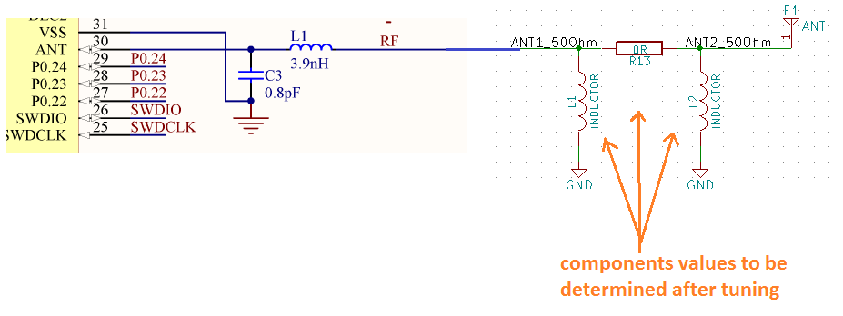
image description

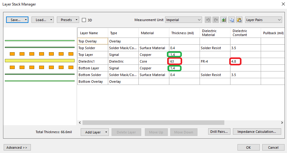
3/ i downloaded the nRF52832-QFAx Reference Layout 1_1 and opened the nRF52832-QFAA project with altuim software. and i want it to check how the antenna track was made and calculate its impedance.

above a screen shot of the values that i got inside altuim :
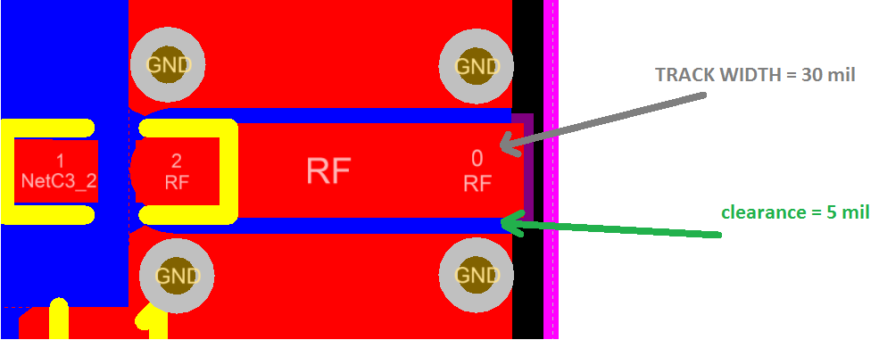
image description

image description

when i tried to calculate the antenna track impedance using theses values i figure out that the track impedance is equal to 46.2851 Ohm and not 50 Ohm ?

below a screen shot of the calculation :
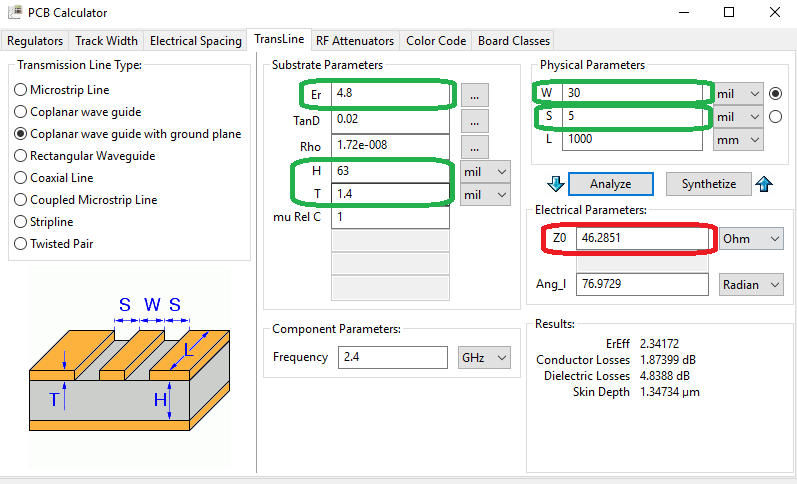
image description

i even used other online tools to calculate the impedance and had the same result

the only way to get 50 Ohm is to change the clearance to 6 mil,
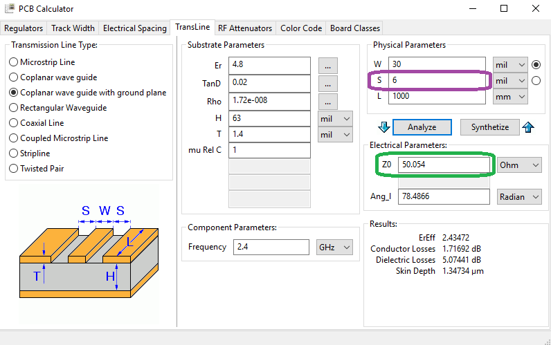
image description

did i do something wrong? any explanation ?

Parents
  • As Jorn mentioned below, Er for standard RoHS FR4 (Tg 170c) generally has a dielectric constant of 4.2 to 4.4. The reality is unless you make that part of your spec the board vendor will not guarantee consistent 50ohm performance. In a spec'd 50ohm situation you tell them which artwork should be 50ohm and they control the board thickness and amount of epoxy vs. glass to get the solution to 50ohm. However, for your purposes don't worry about it. Anything 45 to 55 ohms will be fine. In your calculations you forgot to subtract 2xT from your H value. H is between the outer copper sheets. The outside is 0.062 so H is .062 - .0028 or 0.0592.

Reply
  • As Jorn mentioned below, Er for standard RoHS FR4 (Tg 170c) generally has a dielectric constant of 4.2 to 4.4. The reality is unless you make that part of your spec the board vendor will not guarantee consistent 50ohm performance. In a spec'd 50ohm situation you tell them which artwork should be 50ohm and they control the board thickness and amount of epoxy vs. glass to get the solution to 50ohm. However, for your purposes don't worry about it. Anything 45 to 55 ohms will be fine. In your calculations you forgot to subtract 2xT from your H value. H is between the outer copper sheets. The outside is 0.062 so H is .062 - .0028 or 0.0592.

Children
No Data
Related