This post is older than 2 years and might not be relevant anymore
More Info: Consider searching for newer posts

Antenna tuning with chipset antenna

Hello,

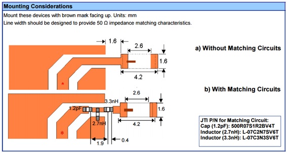
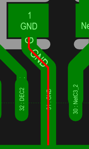
I developed a Nordic board with 2450AT18B100 chipset antenna. I follow the design of Solar Powered Sensor Beacon.

infocenter.nordicsemi.com/index.jsp I test it and it works fine, but I want to tuning the antenna in order to get minimum return lose in signal.

So, I implement this antenna circuit in my board. And
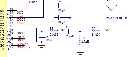
From johanson technology values are: I

I suppose that from C3 and L1 you have to modify some references values of johanson chip antenna.

In general, my questions are:

Can you explain me each part of this circuit?.

Can you explain me why do you change this values and how do you calculated?.

Can you explain me how tuning the antenna?. Because your reference document for that do not explain how to do it in this case.

infocenter.nordicsemi.com/.../nwp_017.pdf

Thanks in advance.

Jose.

Others attached files. Conductor Impedance

image description

Trace Lenght Solar Beacon

image description

Parents
  • Hello Kristin,

    Thanks a lot for your swift reply. I have a new questions...

    How can I measure the output power?.

    About VNA I suppose that the signal of VNA is in C13 and the GND of VNA in L4 (GND), that is right?. About this process...that means that doing that we will be sure about the impedance adaptation between all parts but...what about the frequency resonance?. Imagin that impedance is right but frequency resonance is wrong... I suppose that you make some calculations to do that. Can you shared with us this calculations.

    Thanks in advance.

    Jose.

  • FormerMember
    0 FormerMember in reply to vidal

    Measuring the harmonics: Yes, to measure the harmonics a spectrum analyzer for higher frequencies are needed. If you have copied our reference layout for L1 and C3, with the same component values and distances as in the reference layout, the harmonics will normally not create any problems. The reason why it is necessary to measure the harmonics is to pass the various regulatory standards. All regulatory standards have a maximum limit for signals that are out-of-band.

    Output power: You can use the "radio_test" example in the SDK to easily set the radio in continuous transmission with the desired output power.

Reply
  • FormerMember
    0 FormerMember in reply to vidal

    Measuring the harmonics: Yes, to measure the harmonics a spectrum analyzer for higher frequencies are needed. If you have copied our reference layout for L1 and C3, with the same component values and distances as in the reference layout, the harmonics will normally not create any problems. The reason why it is necessary to measure the harmonics is to pass the various regulatory standards. All regulatory standards have a maximum limit for signals that are out-of-band.

    Output power: You can use the "radio_test" example in the SDK to easily set the radio in continuous transmission with the desired output power.

Children
No Data
Related