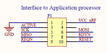
Someone told me that 5V would be fine for prototyping. However I have another problem now; I think I must have wired it wrongly. Because RDY is held low (one spike during setup) - and when the master (Arduino) sets REQ to low, only MISO goes to high (according to my wiring). http://i.imgur.com/0PbGAMo.jpg I assumed that the lower-right pin in P1 is pin 1, because of the printed '1'. So the RDY pin is left, and next to the topmost one. Is this wrong?
Someone told me that 5V would be fine for prototyping. However I have another problem now; I think I must have wired it wrongly. Because RDY is held low (one spike during setup) - and when the master (Arduino) sets REQ to low, only MISO goes to high (according to my wiring). http://i.imgur.com/0PbGAMo.jpg I assumed that the lower-right pin in P1 is pin 1, because of the printed '1'. So the RDY pin is left, and next to the topmost one. Is this wrong?

