
Hi. I am designing PCB based on NRF51822-QFAA-R7. There is 2450BM14E0003T balun will be used. Here is reference design for that pair (NRF51822 + 2450BM14E0003T): www.johansontechnology.com/nordic
According to this design board's stack is following:
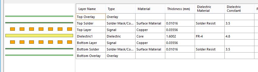
Here is feed trace in the refence design:
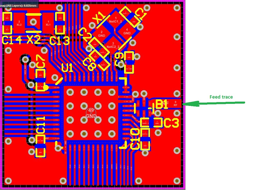
Its width is 0.762mm. I can't understand why??? Calculation gives me that with that trace width (0.762mm) in that design's conditions (Trace Thickness = 0.03556mm; Substrate Height = 1.6mm and Substrate Dielectric = 4.8 ) impedance is 94 Ohm. Not 50 Ohm as there is explained in datasheet for given balun.
I tried to calculate impedance using several calculator, as example using this: www.eeweb.com/.../microstrip-impedance
It seems that pretty easy explanation for that should exist. Explain me please where is the mistake?!

