This post is older than 2 years and might not be relevant anymore
More Info: Consider searching for newer posts

[nRF52] Best practise for ultra low power SAADC 4 channel conversion

What is the best practise for multichannel SAADC conversion in ultra low power devices? For example I have to measured 4 channel in interval 250ms. Below what I try:

  1. I'm set RTC for interupt 250ms. In RTC handler I initialized SAADC channel 0 and start conversion. In SAADC end of conversion handler i uintialized SAADC, get result from channel 0 and initialized for channel 1 and start conversion. Same for channels 3 and 4 but in channel 4 I'm not start new conversion but Im set RTC for 333ms Handler. I try it and I get strange result.

If I have only one channel I've get current consuption: image description

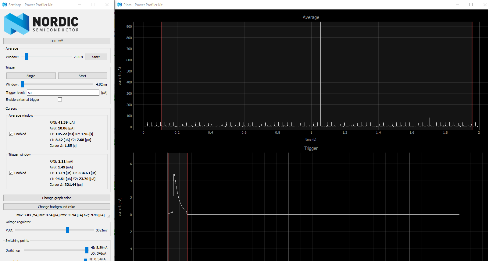
avarage current is around 10uA ( it's ok for my aplication ). but if I enabled conversion for 4 channel, one by one ( as I descripted above ) I've got something like that: image description

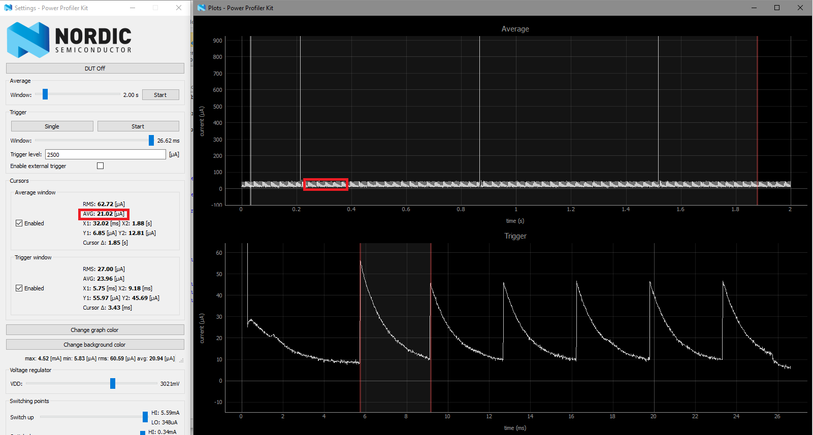
Current is 2 times higher! I don't know why density of the current spikes is in that level.

Mayby I should use PPI? i read this topic: devzone.nordicsemi.com/.../

or maybe different method?

  • Any particular reason you are sampling the channels one by one and not using scan mode? It does look like you are constantly sampling and not having the delay after sampling channel 4, but it is hard to say without seeing any of your code. In general, PPI is great for sampling the SAADC if using scan mode and large buffers, as this will generate less interrupts and leave CPU available for other tasks. But it won't help much on power consumption if you sample channels individually, and if using low power mode, interrupts are needed to uninit SAADC between samples, to limit EasyDMA current.

  • The reason why I'm not using scan mode is tha I can't do this in low power. For example if I try this example: github.com/.../nRF52-ADC-examples for one channel I get 4uA witch it's ok but if I add another channel:

     channel_config2.reference = NRF_SAADC_REFERENCE_INTERNAL;                              //Set internal reference of fixed 0.6 volts
        channel_config2.gain = NRF_SAADC_GAIN1_6;                                              //Set input gain to 1/6. The maximum SAADC input voltage is then 0.6V/(1/6)=3.6V. The single ended input range is then 0V-3.6V
        channel_config2.acq_time = NRF_SAADC_ACQTIME_10US;                                     //Set acquisition time. Set low acquisition time to enable maximum sampling frequency of 200kHz. Set high acquisition time to allow maximum source resistance up to 800 kohm, see the SAADC electrical specification in the PS. 
        channel_config2.mode = NRF_SAADC_MODE_SINGLE_ENDED;                                    //Set SAADC as single ended. This means it will only have the positive pin as input, and the negative pin is shorted to ground (0V) internally.
        channel_config2.pin_p = NRF_SAADC_INPUT_AIN1;                                          //Select the input pin for the channel. AIN0 pin maps to physical pin P0.02.
        channel_config2.pin_n = NRF_SAADC_INPUT_DISABLED;                                      //Since the SAADC is single ended, the negative pin is disabled. The negative pin is shorted to ground internally.
        channel_config2.resistor_p = NRF_SAADC_RESISTOR_DISABLED;                              //Disable pullup resistor on the input pin
        channel_config2.resistor_n = NRF_SAADC_RESISTOR_DISABLED;                              //Disable pulldown resistor on the input pin    
    	
        //Initialize SAADC channel
        err_code = nrf_drv_saadc_channel_init(0, &channel_config);                         0 with the channel configuration
        APP_ERROR_CHECK(err_code);
    		   err_code = nrf_drv_saadc_channel_init(1, &channel_config2);                            
        APP_ERROR_CHECK(err_code);
        if(SAADC_BURST_MODE)
        {
            NRF_SAADC->CH[0].CONFIG |= 0x01000000;    
    NRF_SAADC->CH[1].CONFIG |= 0x01000000;   				
        }
    

    current goes to 900uA. So I decide to try convert channel on by one.

    What I'm doing worong in this example?

  • The SAADC low power example on GitHub should still work in low power mode with multiple channels enabled, you should just have to disable oversampling and burst mode.

  • I'm afraid it's not working :/ Current consumption for one channel is 4uA but for 4 channels above 1mA. I download SAADC low power example from GitHub: github.com/.../saadc_low_power and modify for 4 channels. I disabled burst mode and oversample:

    #define SAADC_SAMPLES_IN_BUFFER 4 
    #define SAADC_OVERSAMPLE NRF_SAADC_OVERSAMPLE_DISABLED 
    #define SAADC_BURST_MODE 0 
    

    I also disable UART_PRINTING_ENABLED and all LED blinking. In this link: www.dropbox.com/.../saadc_low_power.rar you can download modifiy example. What I'm doing wrong?

  • Hi,

    It seems there is some issues with using scan mode when the low-power mode in the SAADC driver is enabled. I will look into this.

    I ported the method used in the saadc_low_power example from SDK 11, and added this to SDK 13 example:

    main.c

    This gives me an average current draw of just over 4 uA.

    Best regards,

    Jørgen

Related