
Hi, I'm deeply interested about the Nordic's PCA20014; a.k.a solar beacon.
This HW uses
-
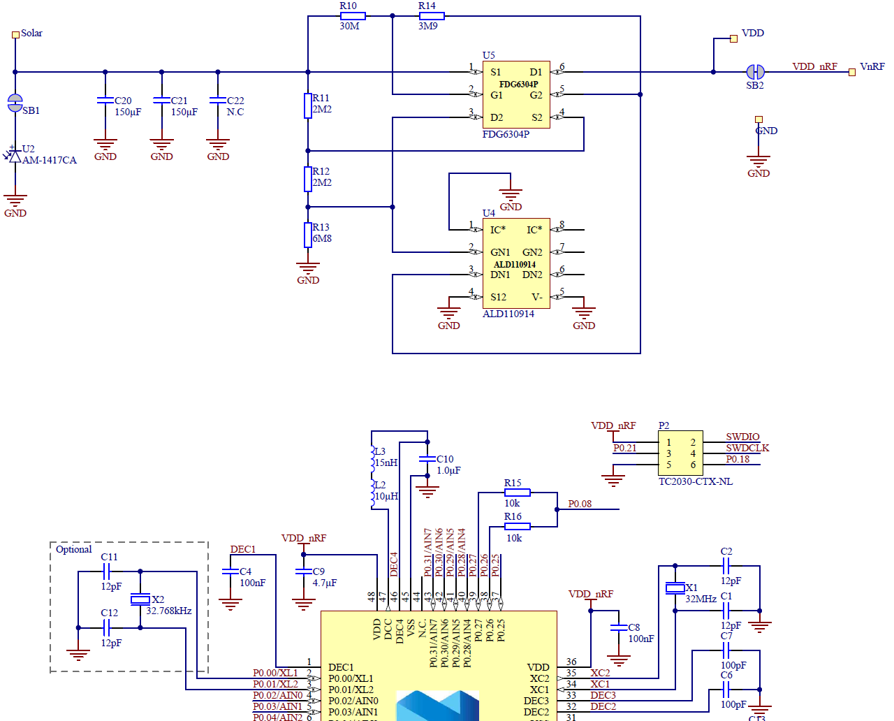
Amorton AM-1417CA solar cell, 1.5V, 12.5uA at FL-200lux
-
2 channel PFET(FDG6304P, typical gate threshold voltage = -0.82V) and NFET(ALD110914SAL, typical gate threshold voltage = 1.40V)
My main concern is using the solar cell with the nRF52 MCU.
In my case, I was thinking of combining the PCA20014 with an I2S Amplifier (MAX98357A).
These are my questions for my investigation before purchasing the PCA20014;
0.Is there a reason for drawing the solar cell as an LED?

At first glance while looking at U2 and the solder bridge, I thought there was an LED that was connected backward.
1.Calculating the voltage dividing resistors, I think the solar cell needs to be charged up to 3V to exceed each gate threshold voltages.
Is there a reverse polarity issue while using the solar cell?
Using my shallow knowledge, I learned that PFETs are mostly used for reverse polarity protection.
I'm curious of the purpose for using 2 PFETs and a NFET.
2.Do these MOSFET works as a voltage regulator?
After opening PFET's gate 2, the divided voltage, 1.5~1.8V will be fed to VDD_nRF, I guess.
I don't see any DC-DC converter or voltage regulators in the schematic.
Does this mean that the voltage provided to the nRF MCU and the pressure fluctuates if the light level changes?
If so, I'm curious whether the MCU can do the job.
3.Since I will be adding an I2S amp, using a bigger solar cell and adding a buck converter will be better for me instead of using the above MOSFETs, right?
4.Switch on/off the external crystal.
The aforementioned statements are written in the Nordic's Infocenter.
Does this mean that this firmware doesn't use the Nordic's SoftDevice and turns on and off the 32MHz, the high-frequency clock, for power saving in the application?
I did check that the GitHub code uses RADIO_IRQHandler.
-Best Regards, MANGO

