This post is older than 2 years and might not be relevant anymore
More Info: Consider searching for newer posts

What precicly is an Element in Bluetooth Mesh

I have a hard time understanding precisely what an Element is and how it differentiates from a Model when talking Bluetooth Mesh.

The only definition can seem to find of an Element is; "Something addressable in a device." But this does not make very much sens to me, since I would think every struct, key and model could be addressable. Also, when should more than one element be used?

I would have imagined there to be some kind of add_element(element_t) function. Are there anything equivalent to this or do I have completely misunderstood how this works?

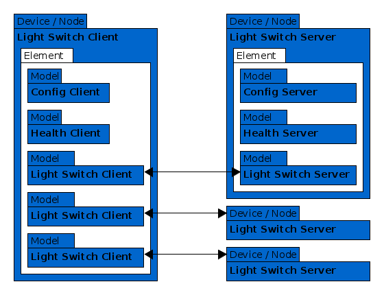
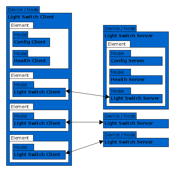
For better understanding elements i would like to know how the Light Switch example is divided into elements. Then i will be able to extrapolate how to design my own project. I have drawn two drawings (A and B) of would I would imagine to be possible examples. And if non of these drawing represent how the example is structured, then how is structured?

A: All models in one element.

A

B: Each model in each own element-

B

EDIT In the example project values like element_index, model_index and model_handle is used very often, but where does values come from? Are they generated by the software? Do i choose them arbitrarily? And which of these values are shared between the provisioner and server on the network?

  • Hi Søren,

    Did you read our introduction to Basic Bluetooth Mesh concepts? There we have tried to explain the concepts of mesh elements and models. Other than that, I would advise you to read the introductory chapters to the Mesh Profile Specification.

    In short, an Element is a single addressable unit in a mesh device. It is the owner of one or more unique states and the models "on" that element define behavior and operations on these states. The classic example is a light fixture with more than one light bulb. That device would require one element for each of the bulbs, as they define the same behavior. Another example is a more advanced light bulb that can do colors in the HSL spectrum. In the Mesh Model Specification a Light HSL Server model is defined to handle this use case. It is an extended model, i.e., it builds upon a common set of other (generic) models. Because you cannot have two instances of a model on a single element (a model is not addressable outside its opcodes), this model requires three elements, one for each of the Hue, Saturation and Lightness states. Have a look at Figure 6.9 on page 255 of the Mesh Model Specification. This also shows the concept of state bindings.

    There is no add_element() call, simply because the number of elements in a device is fixed at compile time and they don't implement any specific behavior themselves, but the models bound to them do.

    Back to your design, drawing "B" best represents the requirement that there can only be one instance of a particular model on any element. Of course, you can define your own models with a more complex state and keep the single element.

    Hope this helps a bit. I would advise you to check out our documentation on the infocenter and the Mesh Profile and Mesh Model specifications. In particular the introductory chapters.

    Answer to your edit:

    • element_index is the local index of an element on the device. It is in the range [0, ACCESS_ELEMENT_COUNT). You are free to place models on whatever element you would like, except for the Configuration Server. A Health Server shall also be supported on the root element (element 0).
    • I couldn't find any usage of model_index, did you mean model_id? The Model IDs are specified by Bluetooth SIG for non-vendor specific models. Otherwise they are specified by the vendor.
    • model_handle is a value used to reference models local to a device. This is a feature of Nordic's nRF5 SDK for Mesh. Instead of referring to models by element index + model ID, you refer to them by their unique model handle (assigned by access.c). This is similar to how the Device State Manager (DSM) assigns dsm_handle_t values (device_state_manager.c) for addresses and keys.

    Best,
    Thomas

  • Hi Thomas, thank you for the explanation. I have some additional questions.

    On Figure 6.9 on page 255 of the Mesh Model Specification, it seems like the "Light HSL Main Element" is inside the "Light HSL Server Model". Is this correct? If it is, how does it work? My understanding was, that models was inside elements and elements was inside node.

    On Figure 2.7 on page 30 of the Mesh Profile Specification, there are a health server inside each of the elements. Now that i see it, it makes sens according to how the configuration is done. But this also means drawing B is incorrect, right?

    On Figure 2.7 the configuration server is inside element 1 together with power level server and the health server. Would it make sens to put the config server inside its own element? And would it then need its own health sever?

  • Hi Søren,

    Models can actually span multiple elements. This is usually the case for Extended models, such as the Light HSL Server, where it extends several of the same generic models, thus separate elements are needed for each of the identical instances within the model. Does that make it more clear to you?

    There is only the requirement that a node shall support the health server on the root element (element 0). Supporting it on additional elements is optional, but would make sense in some cases. Drawing B lacks the configuration server and health server on two of the nodes.

    The configuration server shall always be on the root element of the device (element 0) and as stated above, the health server shall be supported on that element as well. Other than that, you're free to put models wherever you'd like :)

    Hope this helps,
    Thomas

Related