This post is older than 2 years and might not be relevant anymore
More Info: Consider searching for newer posts

NORDIC51822 PWM Settings

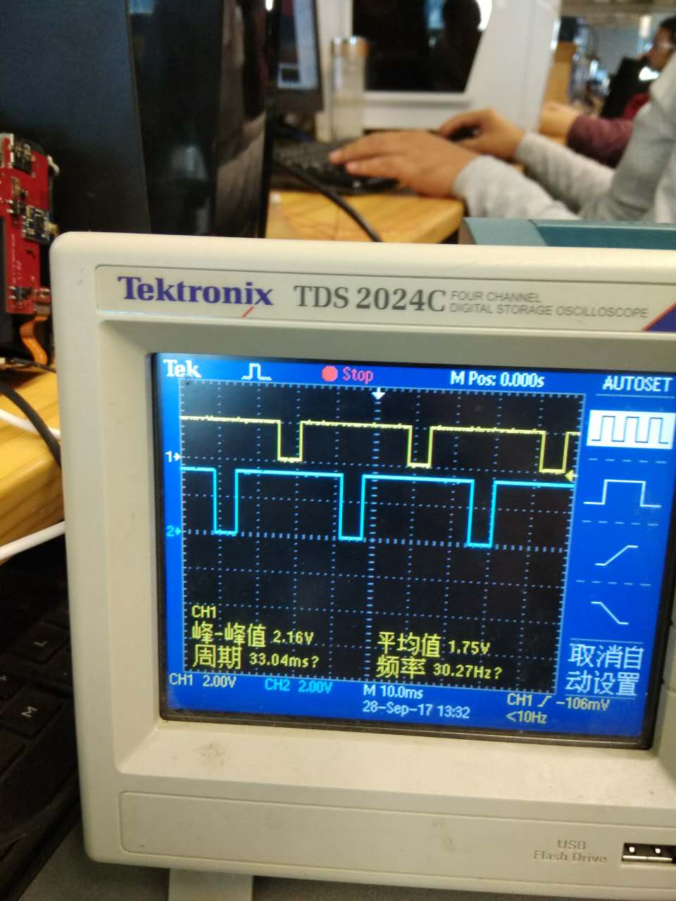
Now want to use two way PWM, how to set the PWM cycle, frequency, duty cycle, there are two road PWM phase, which is the starting point is not the same as shown in figure image description

Based on the Nordic \ nRF5_SDK_12 _f012 2.0

void motor_pwm(void)
{
	
  uint32_t                   err_code;
    nrf_drv_pwm_config_t const config0 =
    {
        .output_pins =
        {
            2| NRF_DRV_PWM_PIN_INVERTED, // channel 0
            25 | NRF_DRV_PWM_PIN_INVERTED, // channel 1
            //5 | NRF_DRV_PWM_PIN_INVERTED, // channel 2
//            BSP_LED_2 | NRF_DRV_PWM_PIN_INVERTED  // channel 3
        },
        .irq_priority = APP_IRQ_PRIORITY_LOWEST,
        .base_clock   = NRF_PWM_CLK_1MHz,
        .count_mode   = NRF_PWM_MODE_UP,
        .top_value    = m_demo1_top,
        .load_mode    = NRF_PWM_LOAD_INDIVIDUAL,
        .step_mode    = NRF_PWM_STEP_AUTO
    };
    err_code = nrf_drv_pwm_init(&m_pwm0, &config0, demo1_handler);
    APP_ERROR_CHECK(err_code);
    m_used |= USED_PWM(0);

    m_demo1_seq_values.channel_0 = 0;
    m_demo1_seq_values.channel_1 = 0;
//    m_demo1_seq_values.channel_2 = 0;
//    m_demo1_seq_values.channel_3 = 0;
    m_demo1_phase                = 0;

    nrf_drv_pwm_simple_playback(&m_pwm0, &m_demo1_seq, 1,
                                NRF_DRV_PWM_FLAG_LOOP);
	
	
}
Parents
  • Hi,

    If you want a simple PWM driver example where you can set the PWM duty cycle directly, then you should take a look at the example linked to in this post.

    The frequency will be F(pwm) = F(clk, e.g NRF_PWM_CLK_1MHz ) / .top_value = #value. E.g. using NRF_PWM_CLK_1MHz, with .top_value =10, you will get 0.1 MHz PWM frequency.

    The duty cycle is will be the ratio between the top_value and seq_value. E.g. if you have .top_value = 10, then you can set seq_value = 5, to get 50% duty cycle.

Reply
  • Hi,

    If you want a simple PWM driver example where you can set the PWM duty cycle directly, then you should take a look at the example linked to in this post.

    The frequency will be F(pwm) = F(clk, e.g NRF_PWM_CLK_1MHz ) / .top_value = #value. E.g. using NRF_PWM_CLK_1MHz, with .top_value =10, you will get 0.1 MHz PWM frequency.

    The duty cycle is will be the ratio between the top_value and seq_value. E.g. if you have .top_value = 10, then you can set seq_value = 5, to get 50% duty cycle.

Children
No Data
Related