This post is older than 2 years and might not be relevant anymore
More Info: Consider searching for newer posts

Is 50 ohm maintained at uFL Connector?

Hello, I am designing a custom board with NRF52832 IC. I followed the same layout design as suggested by Nordic. But , I made some additions to reference layout. I added C3(tuning capacitor) , R7(o ohm) amd CON1(uFL connector to connect VNA) as shown in figure. My idea is to test the RF performance initially without connecting R7 and CON1. If RF performance is not upto my requirement then I would like to connect R7 and CON1.

R7 used in the layout is 0 ohm and 0805 package. And tracewidth of feed line is 30 mils. And tracewidth between R7 and CON1 is also 30 mils.

In this design, I would like to know whether 50 ohm is maintained at uFL connector. And also Can I use 0402 package resistor for R7.

Specifications of my PCB : thickness : 1.6 mm , Dielectric : 4.2, Substrate : FR4
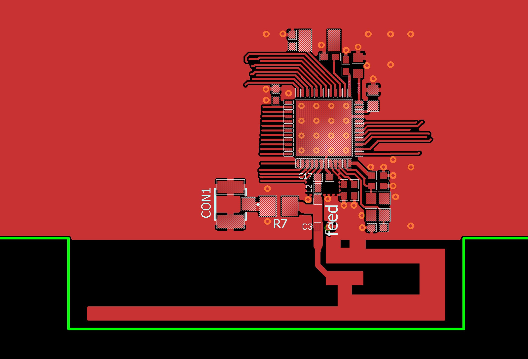
image description

  • Hello SaiTeja

    I would recommend you reconsider the layout here. When not connected the trace leading out to R7, and the pad of R7 will function as a transmission line stub which will severely affect the rest of the system, the trace would have to be physically cut to prevent this. When R7 is connected the antenna will greatly affect the signal leading to the connector and it would have to be physically cut.

    If you look at the nRF52832 DK hardware files you will see this has been solved by using a connector with a built in switch placed as part of the transmission line leading out to the antenna. This way the switch will isolate the antenna from the system when a coax is connected. This gives a compact design while adding as few extra parasitic effects as possible.

    As for component size 0805 is a fairly large package size when working with RF signals, and I would recommend you do not use components larger than 0402 to reduce parasitics.

    Edit

    The connector is from murata, and inside it is a small single pole double throw switch. When the male connector is connected it will trigger the switch inside the female connector, changing the electrical path of the signal within the connector. This allows you to still use the antenna when not using the connector.

    Another way to connect measurement equipment would be to solder the center conductor of a 50 Ohm coaxial cable directly onto the transmission line, however this demands a bit of precision work. The center conductor would have to be as short as physically possible, as the exposed conductor alone would not have a 50 Ohm characteristic impedance. The ground screen of the coax would have to be soldered to the ground of the board, and it too would have to be as short as possible. You would then need to cut the trace leading to the chip as close to the soldered coax as possible.

    Another possibility is to use 0 ohm resistors whose footprint size matches the transmission lines. You could then use two components in a T-junction configuration to choose between either antenna or conductor. You should then try to keep it as small as possible, and keep in mind that parasitics from the resistor could affect your match.

    Best regards

    Jørn Frøysa

  • I didnot understand how component J1 is acting as switch in NRF52 design files. Can you please explain that part . Also it would be really helpful if you suggest other recommended methods for connecting antenna to VNA without parasitic effect (or with minimum possible parasitic effect).

  • I have updated my answer with some additional comments.

  • Thank a lot for suggestions. I would like to go with co-axial cable and solder it directly to antenna. I would like to expose the antenna's beginning (without green silk) to solder the coaxial cable. Can you suggest a coaxial cable?

  • Removing the solder mask should not have any noticeable effect on the RF performance as it is not a conductive material and it's thickness is very small compared to the wavelength of 2.4GHz. Unfortunately I do not have a specific coaxial cable to recommend, however you should go for a semi-rigid type with a characteristic impedance of 50 Ohm. This will make it a bit easier to handle.

Related