This post is older than 2 years and might not be relevant anymore
More Info: Consider searching for newer posts

Is it ok doubler circuit for powering nRF52832 custom board

Hello Everyone,

I have developed my application using BLE for connect android mobile. I have design complete PCB using your reference design. But i have littele confused in power supply schematic because i have use MCP1640 doubler IC, and use only one AA 1.5V battery and converted to 3.3V. my question is i have this attached schematic to powering Nordic chip. Is it sufficient for continuously power to nRF52832 or i need to add any other components with this circuit. I just verify this circuit and hope it will not cause problem in future. I have tested this circuit in general purpose PCB its working fine and that's why i am using in my final design. Any extra energy consumption due this doubler circuit my device current consumption is 4mA-6mA. Please give your valuable suggestion for should i use this
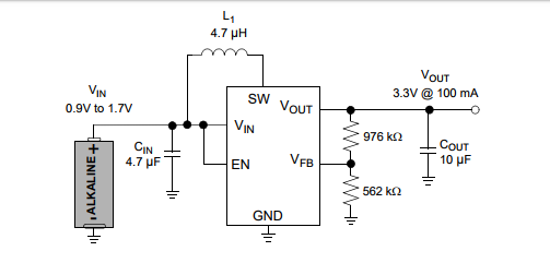
image description.

Parents
  • If you have followed Microchip's reference design I'm sure it should work fine. In the datasheet they claim a quiescent current of maximum 220uA so if you are drawing 4-6mA that suggests that there might be something wrong with your implementation of the nRF52. That current could indicate that your CPU is running continuously. Do you have an oscilloscope or any other way of measuring current over time?

Reply
  • If you have followed Microchip's reference design I'm sure it should work fine. In the datasheet they claim a quiescent current of maximum 220uA so if you are drawing 4-6mA that suggests that there might be something wrong with your implementation of the nRF52. That current could indicate that your CPU is running continuously. Do you have an oscilloscope or any other way of measuring current over time?

Children
No Data
Related