This post is older than 2 years and might not be relevant anymore
More Info: Consider searching for newer posts

Using the SPI example to communicate with a CR95HF

Good evening all, I'm trying to get my DK52 communicating with a CR95HF (this is a NFC controller with serial and SPI control interfaces), I'm using a breakout board - BM019
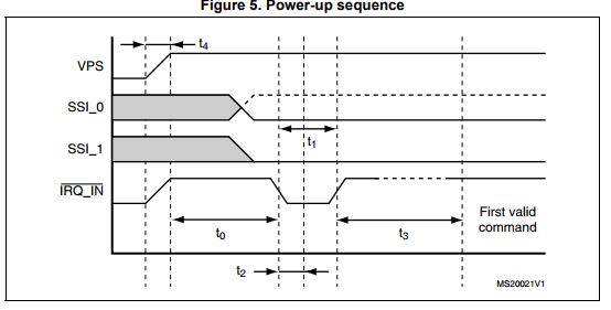
The CR95 requires a setup sequence to select the SPI interface image description

So far I'm using the SPI example from SDK 14, I have modified it to toggle the IRQ_IN pin I'm using pin30) on initialization, I then attempt to send 0x55 to the CR95 (this is a Echo command - I'm expecting 0x55 back). However I seem to get back 0x06 (the first two loops) then nothing for any additional requests)

I have tried removing my initialization toggle, when I do this I don't get anything back on any of the loops)

Here's my modified code.

#define SPI_INSTANCE  0
static const nrf_drv_spi_t spi = NRF_DRV_SPI_INSTANCE(SPI_INSTANCE);  
static volatile bool spi_xfer_done; 

//#define TEST_STRING "Nordic"
//static uint8_t       m_tx_buf[] = TEST_STRING;      
static uint8_t       m_rx_buf[2];  //sizeof(TEST_STRING) + 1];   
static const uint8_t m_length = 1; //sizeof(m_tx_buf);        

void spi_event_handler(nrf_drv_spi_evt_t const * p_event,
                       void *                    p_context)
{
    spi_xfer_done = true;
    NRF_LOG_INFO("Transfer completed.");
    if (m_rx_buf[0] != 0)
    {
        NRF_LOG_INFO(" Received:");
        NRF_LOG_HEXDUMP_INFO(m_rx_buf, strlen((const char *)m_rx_buf));
    }
}

uint8_t hexdata = 0x55;

int main(void)
{
    bsp_board_leds_init();

    APP_ERROR_CHECK(NRF_LOG_INIT(NULL));
    NRF_LOG_DEFAULT_BACKENDS_INIT();
    nrf_gpio_cfg_output(30);
    nrf_gpio_cfg_output(29);
    nrf_gpio_pin_set(30);
    nrf_delay_ms(3000);
    NRF_LOG_INFO("SPI example.");

    nrf_drv_spi_config_t spi_config = NRF_DRV_SPI_DEFAULT_CONFIG;
    spi_config.ss_pin   = SPI_SS_PIN;
    spi_config.miso_pin = SPI_MISO_PIN;
    spi_config.mosi_pin = SPI_MOSI_PIN;
    spi_config.sck_pin  = SPI_SCK_PIN;
    
   nrf_gpio_pin_clear(30);
    nrf_delay_us(100) ;        // BM019 into SPI
    nrf_gpio_pin_set(30);
    nrf_delay_ms(10) ;
    APP_ERROR_CHECK(nrf_drv_spi_init(&spi, &spi_config, spi_event_handler, NULL));
    nrf_delay_ms(1000);
    
    while (1)
    {
        // Reset rx buffer and transfer done flag
        memset(m_rx_buf, 0, m_length);
        spi_xfer_done = false;
        APP_ERROR_CHECK(nrf_drv_spi_transfer(&spi, &hexdata, m_length, m_rx_buf, m_length));
        while (!spi_xfer_done)
        {
            __WFE();
        }

        NRF_LOG_FLUSH();

        bsp_board_led_invert(BSP_BOARD_LED_0);
        nrf_delay_ms(1000);
    }
}

and my output.

<info> app: SPI example.
<info> app: Transfer completed.
<info> app:  Received:
<info> app:  06                     |.       
<info> app: Transfer completed.
<info> app:  Received:
<info> app:  06                     |.       
<info> app: Transfer completed.

I have tried so many thing I'm starting to lose my mind on what I've done! (2 days now!!!) I think i'm initializing it but not 100% sure. I get that this might be a bit out of scope on the Nordic site but I'm thinking this is more a SDK issue!

Parents
  • Hi, I thought I should come back and close this off!

    So after much faffing around I finally got the thing working! As expected user error was the major cause of issues.

    #1) User error - I misunderstood the data sheet - it said that the echo command only had one bit (0x55), that's true, but you also need the control byte (0x00), then poll for answer as all other commands.

    #2) More user error - general messing about with things whilst fault finding.

    #3) ...Probably more user error, but changing the character used to clock stuff out of the CR95HF via SPI from 0xFF to 0x00 fixed 99% of the issues.

    Thanks again for your support :)

  • Hi all! I am having exactly the same issue and don't know how to continue. I have also spend 2 days with this.

    I'm using SDK 15.0 

    My SPI config is as follows:

        nrf_drv_spi_config_t spi_config = NRF_DRV_SPI_DEFAULT_CONFIG;
        spi_config.ss_pin   = NRF_SPI_PIN_NOT_CONNECTED;
        spi_config.miso_pin = SPI_MISO_PIN;
        spi_config.mosi_pin = SPI_MOSI_PIN;
        spi_config.sck_pin  = SPI_SCK_PIN;
        spi_config.orc      = 0xFF;
        spi_config.mode      = NRF_DRV_SPI_MODE_0;
        spi_config.frequency = NRF_DRV_SPI_FREQ_1M;
        spi_config.bit_order = NRF_DRV_SPI_BIT_ORDER_MSB_FIRST;
        
        APP_ERROR_CHECK(nrf_drv_spi_init(&m_spi_master_0, &spi_config, spi_event_handler, NULL));
        
        nrf_gpio_pin_set(IRQ_PIN);
        nrf_gpio_pin_set(SPI_SS_PIN);
    
       // CR95HF Wake-Up Pulse
       nrf_delay_ms(10);                        // send a wake up
       nrf_gpio_pin_clear(IRQ_PIN);      // pulse to put the
       nrf_delay_us(100);   
       nrf_gpio_pin_set(IRQ_PIN);     // mode
       nrf_delay_ms(10); 

    I know it might be overkill configuring SS manually but I'm porting code from arduino and it is done like that over there.

    The CR95HF SPI works in 3 steps:
    1. send command
    2. poll with 0x03 until SPI return bit 4 to 1
    3. send command 0x02 to read

    The corresponding arduino code of step 1 and 2 is:

    // step 1 send the command
      digitalWrite(SSPin, LOW);
      SPI.transfer(0x00);  // SPI control byte to send command to CR95HF
      SPI.transfer(0x02);  // Set protocol command
      SPI.transfer(0x02);  // length of data to follow
      SPI.transfer(0x01);  // code for ISO/IEC 15693
      SPI.transfer(0x0D);  // Wait for SOF, 10% modulation, append CRC
      digitalWrite(SSPin, HIGH);
      delay(1);
     
    // step 2, poll for data ready
    
      digitalWrite(SSPin, LOW);
      while(RXBuffer[0] != 8)
        {
        RXBuffer[0] = SPI.transfer(0x03);  // Write 3 until
        RXBuffer[0] = RXBuffer[0] & 0x08;  // bit 3 is set
        }
      digitalWrite(SSPin, HIGH);
      delay(1);

    So my ported code looks like this:

    uint8_t invcommand[5] = {0x00, 0x02, 0x02, 0x01,0x0D};

    nrf_gpio_pin_clear(SPI_SS_PIN);
    spi_xfer_done = false;
    APP_ERROR_CHECK(nrf_drv_spi_transfer(&m_spi_master_0, &invcommand, 5, m_rx_buf, 5));
    while (!spi_xfer_done)
    {
      __WFE();
    }
    nrf_gpio_pin_set(SPI_SS_PIN);
    nrf_delay_ms(1);
    
    nrf_gpio_pin_clear(SPI_SS_PIN);        
    while(m_rx_buf[0] != 8) {
      spi_xfer_done = false;
      m_tx_buf[0] = 0x03;
      APP_ERROR_CHECK(nrf_drv_spi_transfer(&m_spi_master_0, m_tx_buf, 1, m_rx_buf, 1));
      while (!spi_xfer_done)
      {
        __WFE();
      }
      
      m_rx_buf[0] = m_rx_buf[0] & 0x08;
    }
    nrf_gpio_pin_set(SPI_SS_PIN);
    nrf_delay_ms(1);
            

    But it never gets out of the STEP 2 while loop and the SPI keeps returning 0x06

    I'm hoping to get my hands on a logic analyser and see how the signals on arduino vs DK52 look like.

    As for the sdk_config.h SPI data:

    NRFX_SPIM_ENABLED 1
    NRFX_SPI_ENABLED 1
    SPI_ENABLED 1
    SPI0_ENABLED 1
    SPI0_USE_EASY_DMA 1
    

Reply
  • Hi all! I am having exactly the same issue and don't know how to continue. I have also spend 2 days with this.

    I'm using SDK 15.0 

    My SPI config is as follows:

        nrf_drv_spi_config_t spi_config = NRF_DRV_SPI_DEFAULT_CONFIG;
        spi_config.ss_pin   = NRF_SPI_PIN_NOT_CONNECTED;
        spi_config.miso_pin = SPI_MISO_PIN;
        spi_config.mosi_pin = SPI_MOSI_PIN;
        spi_config.sck_pin  = SPI_SCK_PIN;
        spi_config.orc      = 0xFF;
        spi_config.mode      = NRF_DRV_SPI_MODE_0;
        spi_config.frequency = NRF_DRV_SPI_FREQ_1M;
        spi_config.bit_order = NRF_DRV_SPI_BIT_ORDER_MSB_FIRST;
        
        APP_ERROR_CHECK(nrf_drv_spi_init(&m_spi_master_0, &spi_config, spi_event_handler, NULL));
        
        nrf_gpio_pin_set(IRQ_PIN);
        nrf_gpio_pin_set(SPI_SS_PIN);
    
       // CR95HF Wake-Up Pulse
       nrf_delay_ms(10);                        // send a wake up
       nrf_gpio_pin_clear(IRQ_PIN);      // pulse to put the
       nrf_delay_us(100);   
       nrf_gpio_pin_set(IRQ_PIN);     // mode
       nrf_delay_ms(10); 

    I know it might be overkill configuring SS manually but I'm porting code from arduino and it is done like that over there.

    The CR95HF SPI works in 3 steps:
    1. send command
    2. poll with 0x03 until SPI return bit 4 to 1
    3. send command 0x02 to read

    The corresponding arduino code of step 1 and 2 is:

    // step 1 send the command
      digitalWrite(SSPin, LOW);
      SPI.transfer(0x00);  // SPI control byte to send command to CR95HF
      SPI.transfer(0x02);  // Set protocol command
      SPI.transfer(0x02);  // length of data to follow
      SPI.transfer(0x01);  // code for ISO/IEC 15693
      SPI.transfer(0x0D);  // Wait for SOF, 10% modulation, append CRC
      digitalWrite(SSPin, HIGH);
      delay(1);
     
    // step 2, poll for data ready
    
      digitalWrite(SSPin, LOW);
      while(RXBuffer[0] != 8)
        {
        RXBuffer[0] = SPI.transfer(0x03);  // Write 3 until
        RXBuffer[0] = RXBuffer[0] & 0x08;  // bit 3 is set
        }
      digitalWrite(SSPin, HIGH);
      delay(1);

    So my ported code looks like this:

    uint8_t invcommand[5] = {0x00, 0x02, 0x02, 0x01,0x0D};

    nrf_gpio_pin_clear(SPI_SS_PIN);
    spi_xfer_done = false;
    APP_ERROR_CHECK(nrf_drv_spi_transfer(&m_spi_master_0, &invcommand, 5, m_rx_buf, 5));
    while (!spi_xfer_done)
    {
      __WFE();
    }
    nrf_gpio_pin_set(SPI_SS_PIN);
    nrf_delay_ms(1);
    
    nrf_gpio_pin_clear(SPI_SS_PIN);        
    while(m_rx_buf[0] != 8) {
      spi_xfer_done = false;
      m_tx_buf[0] = 0x03;
      APP_ERROR_CHECK(nrf_drv_spi_transfer(&m_spi_master_0, m_tx_buf, 1, m_rx_buf, 1));
      while (!spi_xfer_done)
      {
        __WFE();
      }
      
      m_rx_buf[0] = m_rx_buf[0] & 0x08;
    }
    nrf_gpio_pin_set(SPI_SS_PIN);
    nrf_delay_ms(1);
            

    But it never gets out of the STEP 2 while loop and the SPI keeps returning 0x06

    I'm hoping to get my hands on a logic analyser and see how the signals on arduino vs DK52 look like.

    As for the sdk_config.h SPI data:

    NRFX_SPIM_ENABLED 1
    NRFX_SPI_ENABLED 1
    SPI_ENABLED 1
    SPI0_ENABLED 1
    SPI0_USE_EASY_DMA 1
    

Children
Related