
i have a particular automotive tuning application where i have to deal with ignition and fuel injection timing (old stuff in the new e-mobility time)
here are some loose specs
a single injector has a min on time of about 1 ms at a min repetitive period of 7 ms and i need to support a minimum of 4, reading 4 input timings and outputting 4
the crank sensor can have a min pulse timing of 300 us, one timing in and one out
and i need to shift them all around and make them longer or shorter individually
i have done this many times before having plenty of timer cap-comps available which work directly off pins
also what's the absolute max time the softdevice is stealing from my high priority intrs ... i read something about 235 us, which means to me that i can't respond faster than, let's say 270 us, if i have to do some simple number crunching on timer capture input timing measurements versus outputting the change
i would need to have the crank sensor on timer cap/comps supported by gpiote and ppi which eats up at least one gpiote channel since this is a timing sensitive signal
now i'm short one at least to support reading 4 injector in timings and outputting them with a changed timing using gpiote channels
i think i absolutely need some of the remaining gpiote channels for the input timing measurements using timer cap regs and ppi
is there any way to hijack other peripherals pin support to link the timer comp event to it to flip the pins ... i was thinking about the pwm or similar ... you guys know your peripherals best
i was initially very happy counting all timer cap/comps totalling 20 (2 x 4 + 2 x 6)
now is the wakeup from this timer dream and it seems that the 8 gpiote channel limitation renders the vast amount of timer cap/comps a waste
maybe i'm missing something but how can all these cap/comps be used without i/o support
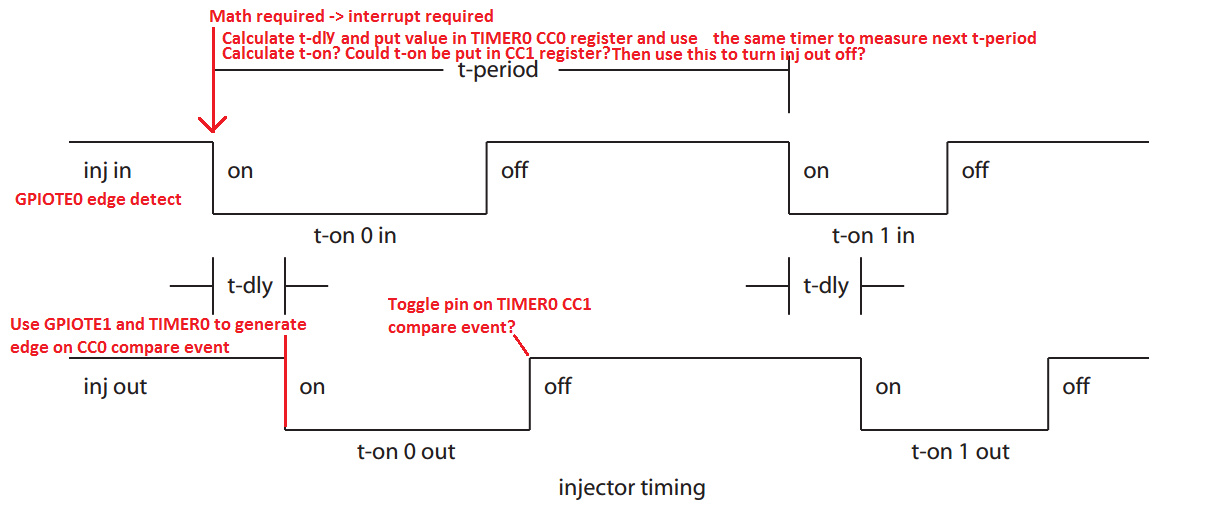
injector timing :
there is a total of 4 (desirable 6) injectors and their timing is independent of each other
t-period times are different on all periods due to rpm variations
the inj-in on-time needs to be stored for 2 reasons
one being that the inj-out on-time is a const t-dly time delay later output
second being used for the inj-in t-on duration measurement
the inj-out t-on duration is calculated based upon t-on in and some adjustment from an rpm / maf-sensor map
the inj t-period will vary between 7 ms to 200 ms
the shortest t-on time is about 1 ms
t-adj is about the shortest t-on duration, 1 ms
crank sensor timing : only one sensor
t-period times are different on all periods due to rpm variations
the only important timing is the pulses leading edge time which is to be output at a delayed time later based upon a calculation from the crank sensor t-period which is a fraction of the engine rpm and an ignition data map value
there is usually one tick for every 360 deg missing to provide a crank position indication
the shortest crank sensor t-period is about 300 us at max rpm
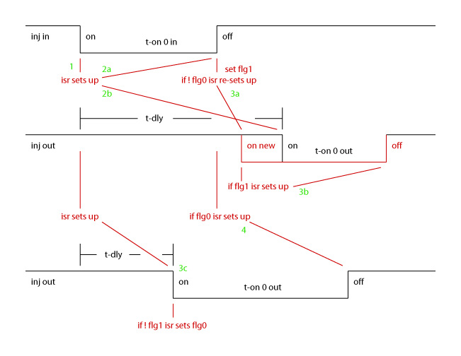
this is a new pict of the injector timing relations ... please find the description below the pict
- gpiote-ch0 and timer1-cc0 are being set up for capturing the leading edge-on inj0-in event
2a) capturing isr for item 1 (leading edge-in cc) sets up the capture of edge-off inj0-in on the same gpiote and timer1 cc0 ... this ties up one gpiote channel and one timer1 cc reg
2b) it also sets up the leading edge-on inj0-out delayed on-time on gpiote ch1 and timer1 cc1
now totaling 2 gpiote channels and 1/2 timer1 (cc0 for iput capture and cc1 for output compare) for a single injector
3a) there are now 2 scenarios possible ... capture edge-off inj0-in event (end of input pulse) happens before expiration of time delayed leading edge-on inj0-out event (start of output pulse)
capturing isr for edge-off inj0-in event will overwrite the already setup delayed inj0-out time to a bit more than the possible max softdevice isr latency time after the current timer value ... this will define the final leading event-on inj0-out time
since this isr captured the edge-off inj0-in event, it now also sets up for the next leading edge-in inj0-in event capture at item 1
3b) afterwards, the new time delayed edge-on event inj0-out isr will set the edge-off inj0-out time
3c) second scenaro is that the time delayed leading edge-on inj0-out event happened before the edge-off inj0-in event
this event sets a flag for the edge-off inj0-in isr to indicate that the delayed out event already happened
- the edge-off inj0-in isr has the flag and the inj0-in pulse duration and can now set the edge-off inj0-out time, it also sets up for the next leading edge-on inj0-in event capture at item 1
any thoughts and help are always highly appreciated
cheers Klaus

