This post is older than 2 years and might not be relevant anymore
More Info: Consider searching for newer posts

TWI ISSUE !

Hello,

I have an issue with a nRF51822 TWI. I am using the "TWI sensor example application" as a base code.

The TWI module seems to powered, enabled and ready to communicate (see figure below)

image description

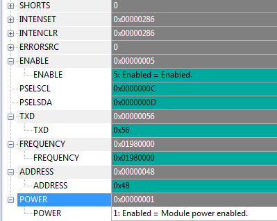
The PIN set is also correct and the address as well (7 bit address). I also created another project to check my IO using the GPIO module.

On the other side of the bus stands a ADS1115.

Unfortunately, I can not get any signal on SCL and SDA (I am using logic analyser to monitor the bus)

And I can not get any ACK from the ADS1115.

My module instantiation is also correct, no SPI using the same address as the TWI module (0x40003000).

I already had a look on the forum but no answers help me to solve the problem.

Does anyone has an idea to help me, please ?

Best regards

Parents
  • before you remove the pull-ups, try setting the frequency to 400 instead of 100 . on some sensor this helped me. In my case I had pull-ups on the main pcb holding the NRF and additional ones on the connected sensor pcb - this was dividing the resitors with each additional board attached. you could try what happens if you connect the ADS to 5V if you have it on the pcb. if it starts working and the IC is 5V tolerant, then your problems are the pull-ups...

Reply
  • before you remove the pull-ups, try setting the frequency to 400 instead of 100 . on some sensor this helped me. In my case I had pull-ups on the main pcb holding the NRF and additional ones on the connected sensor pcb - this was dividing the resitors with each additional board attached. you could try what happens if you connect the ADS to 5V if you have it on the pcb. if it starts working and the IC is 5V tolerant, then your problems are the pull-ups...

Children
Related