This post is older than 2 years and might not be relevant anymore
More Info: Consider searching for newer posts

No response from the PPK,why?

dear nordic employee:

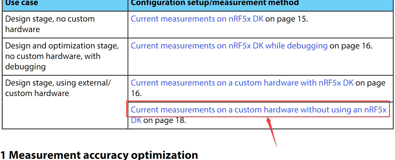
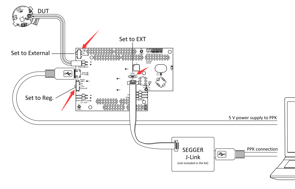
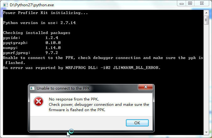
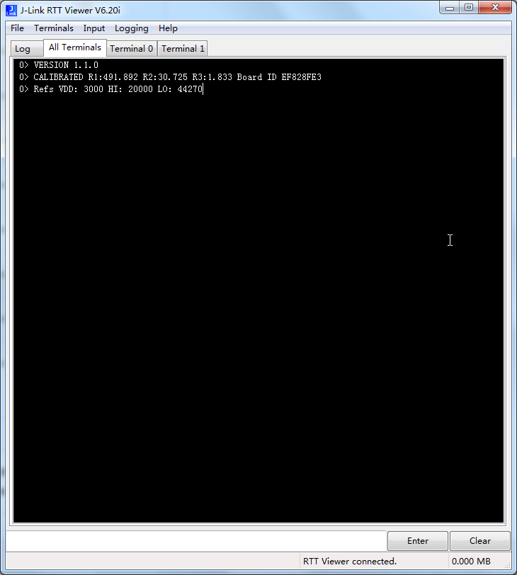
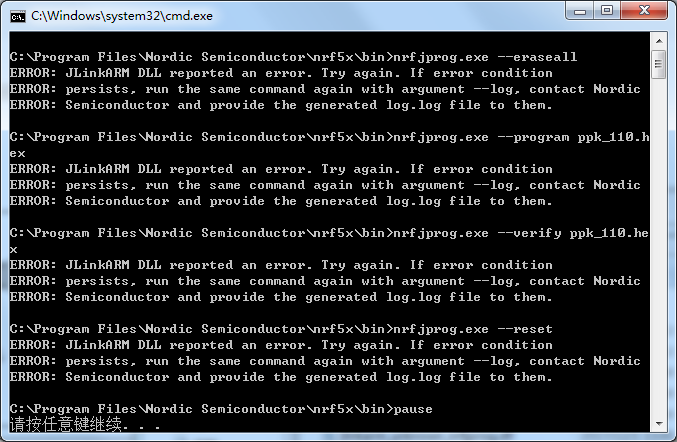
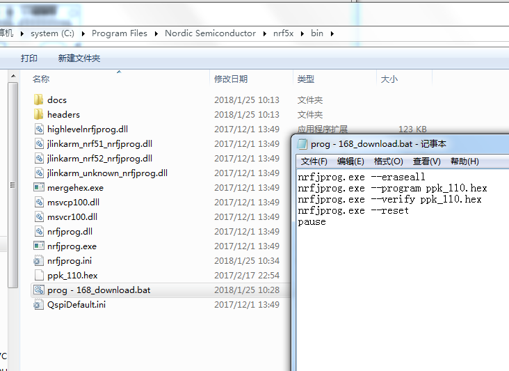
I want to use the PPK measure my hardware I set as the 《PPK_User_Guide_v1.1》 says,and the led1 is ok but the ppk cannot work well the details like the picture shows

1.png 2.png ppkwrong.png RTT.png

DOWNLORD WRONG.png DOWNLORD SETTING.png regards

  • If you have an nrf5x dev kit, have you tried to measure the current on the nrf5x dk? Here is a quick start guide for that. I just want to make sure that the ppk is working with the simplest configuration first. Can you start the python executable then? From your image 2.png, it seems that you have setup the ppk correctly. From the error message in ppkwrong.png, it seems that there might be a faulty connection between your Segger J-Link and the Debug In port on the PPK. Also check the cables between the External DUT connection on the PPK & your external HW. Is there any power on your external HW (e.g. any lights that are on)? Also, have you flashed the FW to the PPK?

  • hi Bjørn Kvaale

    thanks for your reply

    I click the convert to answer button by mistake

    1、I donot have a nrf5x dk from nordic

    2、“Also check the cables between the External DUT connection on the PPK ”

    A:like the “RTT.png” shows ,when I connect the PPK and computer by jlink,the rtt can print the information,so I think the connection is ok

    3、“Is there any power on your external HW (e.g. any lights that are on)”

    A:yes, my HW is power on,but I think the PPK will work well even it has not connect with a HW,is it right?

    4、“have you flashed the FW to the PPK?”

    A:like the point 2 says,the rtt can print the FW information when I connect the PPK and computer by jlink debuger,so I think the PPK is work well

  • Hi victor_CHINA. Got a tip from a colleague here: What if you try switching the COM switch in the middle of the PPK board to DK instead of EXT? What happens then? I have tried to test this exact setup, but have not gotten it working yet. Will let you know once I figure it out.

  • Got it working now! I used an nrf52dk as the external device under test (DUT). What I did was first program the application on the external DUT via the built in jlink on the nrf52dk. For your use case, you can use the Segger J-Link in the figure you uploaded to program the external DUT. Then, I turned off the external DUT & set up the cables like in the figure. I used another 52DK as my Segger J-Link & connected the SWD cable via the P19 debug out port on the dk. You can just use your Segger J-Link and connect the SWD cable to the Debug In port on the PPK. Remember to set the DUT select switch to External & the Power Select switch to Reg. (both of these switches are on the PPK). Set the COM switch on the PPK to DK instead of EXT! Finally, connect the External DUT positive pin on the PPK to the positive pin on the external supply of your DUT & the negative pin on the External DUT on the PPK to the negative pin of the external supply on your DUT. Remember to power both the Segger J-Link and the PPK via two separate USB cables.

    Since the COM switch on the PPK is in the DK position, when you run flash_ppk.py, you will program the PPK and not the external DUT. Once that has completed successfully, run the ppk.py file & the PPK SW should start. Remember to use Python 2.7. Hope that helps!

Related