This post is older than 2 years and might not be relevant anymore
More Info: Consider searching for newer posts
This discussion has been locked.
You can no longer post new replies to this discussion. If you have a question you can start a new discussion

Crash on connecting second I2C module

Hi,

I'm connecting two I2C modules : MAX30102 and MPU-9250

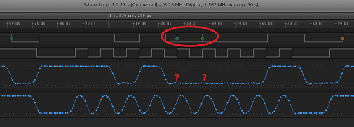
I can individually communicate with either of these modules and they work okay. But if I connect both of them together on the same bus, only the MAX30102 works. The other module fails to communicate. I see the following on the Logic Analyzer:

image description

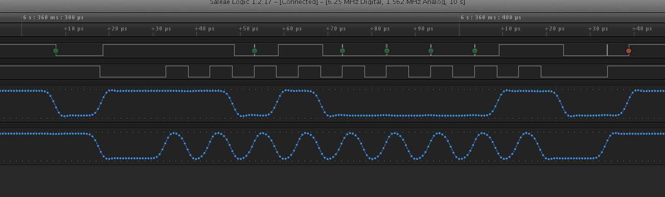
I flashed again, and I get a different behaviour:

image description

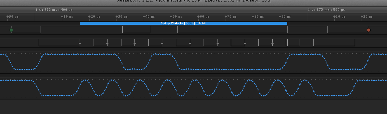
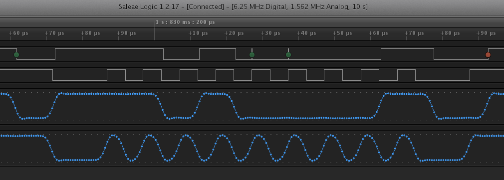
There is a small pulse in the SCL line towards the end. If I reset the board, I get a mix of ACKs and NACKs for write to different registers, but no consistent communication:

image description

The MAX30102 module has an inbuilt level shifter, and it pulls the I2C bus to VIN, which is 2.8v coming from the NRF52-DK. But MPU9250 module did not come with a schematic, but I'm assuming it to be pulled up to 2.8V itself, since its VIN is the same 2.8V from NRF52-DK.

If I disconnect SDA/SCL of MAX30102, then MPU9250 start communicating consistently. Could anyone point out why the communication is inconsistent ?

Parents
  • There is a picture of a schematic for you MPU9250 module in your link. It shows that there is a 3.3V voltage regulator between Vin and the MPU. There is likely a voltage drop across that regulator that could make life difficult for the MPU. I suggest that you short the solder bridge next to the regulator to bypass the regulator and make sure that power the MPU directly from Vin.

    asd

    These two spikes are quite weird though. Do you know where they come from?

    Are you using your own code? Have you tried a simple example to test basic functionality?

Reply
  • There is a picture of a schematic for you MPU9250 module in your link. It shows that there is a 3.3V voltage regulator between Vin and the MPU. There is likely a voltage drop across that regulator that could make life difficult for the MPU. I suggest that you short the solder bridge next to the regulator to bypass the regulator and make sure that power the MPU directly from Vin.

    asd

    These two spikes are quite weird though. Do you know where they come from?

    Are you using your own code? Have you tried a simple example to test basic functionality?

Children
No Data
Related