This post is older than 2 years and might not be relevant anymore
More Info: Consider searching for newer posts

How to serial debug custom nrf51 chip via Development Kit USB?

Hi everyone, I've read some nordic forum articles on this topic but somehow I just dont get information I need. 

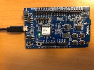
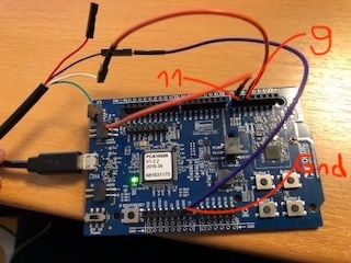
I can flash my custom nrf51822 chip by using my nrf51422-DK (PCA10028). I simply connect to P20 as follows:

P20-DK_VTG ==> chip_VDD

P20-DK_SWD_IO ==> chip_SWDIO

P20-DK_SWD_CLK ==> chip_SWD_CLK

P20-DK_GND ==> chip_GND

I can flash it with a "hello world" program, e.g. making an LED blink on the custom board. Also the nrfStudio shows nrf51822 (with the digit 8) when I connect the custom board to the Development Kit and it shows nrf51422 (with the digit 4) when I disconnect the custom board. So far so good.

However, when the simple "hello world" application runs on my custom board (nrf51822), I want to serial print on my PC console some random text via my DK. What I mean is, the custom board sends the example text "hello world" to the DK, and the DK sends it via USB to my PC console. Just to make it clear: I do NOT want to use BLE, but instead just cables.

This "hello world" string has to be sent via a predefined PIN_SERIAL_TX. Am I correct?

If yes, whatever pin I define to be my PIN_SERIAL_TX, this pin is actually not connected at all to my DK. Because so far I have only the 4 connections above (VTG, SWDIO, SWDCLK, GND). Do I have to connect that pin to P20 of my DK in order to serial print? If yes, where to? Is it SWO then?

If I am wrong with my assumptions and the 4 connections (VTG, SWDIO, SWDCLK, GND) are sufficient enough, then how to tell the custom board to send a "hello world" string to the DK and how to tell the DK to send it to the PC console?

Can anyone help pelase? I would really 
appreciate some guidance.

Parents
  • 2 ways to perform your "cable" test:

    (a) hook up your custom board to your pc through a "USB to TTL serial cable: (eg. https://www.adafruit.com/product/70). Install the driver in your pc, then fire up, say, the putty to display the "hello world" from your custom board. You also need to initialize the uart in your custom board of course.

    (b) keep to the [  pc <--- usb ---> PCA10028 <-- SWD --> custom board  ] configuration but enable segger rtt in your hello-world application code and call the SEGGER_RTT_printf() to send your debug messages out. On your pc side launch the segger rtt viewer to display the messages from your custom board.

    I used both in my nRF52 sdk12 work before; should work for nRF51 also.

  • Hi Matt I bought a USB TTL Adapter Cable.

    The cable has the follwoing pins:

    Red - 3.3V
    Black - Gnd
    White - RxD
    Green - TxD

    I tried two things:

    1) I flashed my Nrf51422-DK (PCA10028) with a simple program printing "Hello there" on the console. When I connect the DK normally via its USB cable:

    Then it prints it out, saying "Hello there". So far so good.

    The DK's pin definitions are:

    P0.08 = RTS

    P0.09 = TXD

    P0.10 = CTS

    P0.11 = RXD

    So I took the cable that I bought and connected it as follows:

    Cable Black: Gnd ====> Nrf51 Gnd
    Cable White: RxD====> Nrf51 - P0.09 = TXD
    Cable Green: TxD====> Nrf51 - P0.11 = RXD

    I guess I can just forget about the RTS / CTS pins. Correct?
    I am using "Terminate 3.3" in order to print out the incoming serial data. And in my settings I chose no flow control:
    Flow control: "none". And it worked in the first case above (normal DK USB connection).

    While my DK still gets its power from the normal USB connection, I dont need to use the Red Pin (3.3V) from the bought cable.

    ==> But I dont get any data via this cable. I dont know why.

    2) The second thing that I tried is actually the same "hello there" program that prints it out on the console but with another Nrf51822 chip on a square board. There I connected it as follows:

    Cable Red: 3.3V ====> Nrf51 VDD
    Cable Black: Gnd ====> Nrf51 Gnd
    Cable White: RxD====> Nrf51 - P0.09 = TXD
    Cable Green: TxD====> Nrf51 - P0.10 = RXD

    On this board I just had to change to RXD --> P0.10.

    P0.09 = TXD

    P0.10 = RXD


    Additionally I made an LED blink via P0.12 in order to know that I flashed this chip correctly. The LED blinks as expected but I still dont get any serial data ("Hello there" in this case) from the chip.

    How can I make this work? 

  • The PC10028 connections look fine (I use PCA10040 and the pin numbers are different). I suggest you use the coin cell battery to power the DK. And make sure you see the com port when you hook up the USB TTL serial cable (open device manager and check com port if you're using windows). Try baud rate 57600 8N1 no flow control on both ends (putty on windows, and uart_init() in your nRF51)

    As for the square board (again I only have the nRF52 square one) make sure you connect to the correct pin 9 and 11 (for my nRF52 square board the pins 6 & 8 are on the left hand side).

Reply
  • The PC10028 connections look fine (I use PCA10040 and the pin numbers are different). I suggest you use the coin cell battery to power the DK. And make sure you see the com port when you hook up the USB TTL serial cable (open device manager and check com port if you're using windows). Try baud rate 57600 8N1 no flow control on both ends (putty on windows, and uart_init() in your nRF51)

    As for the square board (again I only have the nRF52 square one) make sure you connect to the correct pin 9 and 11 (for my nRF52 square board the pins 6 & 8 are on the left hand side).

Children
No Data
Related