This post is older than 2 years and might not be relevant anymore
More Info: Consider searching for newer posts

J-Link Programming external nRF52 : Failed to connect to target, no Idcode detected

Hi,

I'm currently programming a custom board using a nRF52832 (using this wiring). Everything was working great but I tried to play with SAADC and maybe did a wrong configuration and/or added too much debug log. Since a previous code upload, I'm unable to connect to my board again.

I had another board with the same behavior (same code uploaded to confirm this was the code), but somehow I found a way to unlock it, I was able to upload a basic blinky example while removing the GND DETECT and switch from VDD to VDD nRF. I don't know if it related though.

But I still have one board completely locked, how to unlock it ?
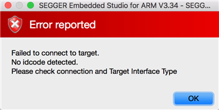
> JLinkExe -device NRF52 -if SWD -speed 1518 -autoconnect 1

SEGGER J-Link Commander V6.22a (Compiled Nov 28 2017 17:57:01)
DLL version V6.22a, compiled Nov 28 2017 17:56:49

Connecting to J-Link via USB...O.K.
Firmware: J-Link OB-SAM3U128-V2-NordicSemi compiled Jul 24 2017 17:30:12
Hardware version: V1.00
S/N: 682621274
VTref = 3.300V
Device "NRF52" selected.


Connecting to target via SWD
Cannot connect to target.
J-Link>

Thanks

  • Hi,


    Since it detects 3.3V, it looks like you have the wiring setup correctly.

    Have you tried using nrfjprog to recover the device, like this: "nrfjprog --recover -f nrf52"?

    The current consumed by your custom board can also be a good indicator if there's something wrong. Have you checked this?

    Cheers,

    Håkon

  • Hi Håkon,

    Yes I tried it, here are the log :

    > nrfjprog --recover -f nrf52
    
    Recovering device. This operation might take 30s.
    ERROR: Recover failed. Please make sure that the correct device family is given
    ERROR: and try again.

    About the current consumption I'm not sure how I should measure it, I'm more a software person. But as far as I checked, there was no difference on the board compared to a functional one.

    For a broken and working board results are the same, plugged to the nRF52DK, I have 2.79V coming out of the regulator and the VDD, VDD_2 and VDD_3 of the nRF52 are 2.79V.

    I checked the VDD coming out of the nRF52DK : 2.82V.

  • Hi Håkon,

    Did you had the time to check my previous reply ? I'm still not able to find a solution by myself :/ 

    Thanks for your support

  • Hi,

    I am sorry for the late reply.

    Just as a reference, you can find how to measure current in the DK user-guide:

    Measuring current

    Note: if this board has been used for current measurements before, it is likely that the SB9 is already been cut. In this case, you need to short header P22.

    Since you measure 2.8V on VDD_NRF, this should be fine on your kit.

    Did you connect the pins "VDD" and "VTG"? This is required for external programming, if not; the SEGGER device will try to program the nRF on the development kit.

    Pins "VTG" and "GND_DETECT" are actually ADC-input pins, and should not be confused with GND and VDD, as these pins will not provide power to your external board.

    Also, could you make sure that you have the latest nrfjprog? latest one is v9.7.2: nRF5x-Command-Line-Tools-OSX


    Best regards,

    Håkon

  • Hi ,

    I measured the current for both working and broken custom board, same result : 2.06V

    VDD and VTG are well connected since I'm already able to program other boards.

    About nrfjprog :

    > nrfjprog -v
    nrfjprog version: 9.7.2
    JLinkARM.dll version: 6.22a

    Hope this help you help me :)

    Thanks

Related