
Hello DevZone,
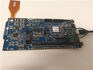
I am using a nRF52840 for project development.
To test SPI setting is correct or not, I am doing the loop-back test, I set the MISO and MOSI PIN according to Arduino UNO compatible PIN map. But when I run the nRF52 program, I found some strange appearances.
In the nRF52 program, there are two successive SPI transfer calls(spi_send_recv()):
Code:
...
spi_send_recv(p_instance, 0xA0, dummy, 1);
spi_send_recv(p_instance, 0x00, i, 1);
...
static void spi_send_recv(nrf_drv_spi_t const *const p_instance, uint8_t p_tx_data, uint8_t p_rx_data, uint8_t len)
{
uint8_t tx_data = p_tx_data;
SEGGER_RTT_printf(0, "tx data %x\n", tx_data);
uint32_t err_code = nrf_drv_spi_transfer(p_instance, &tx_data, len, &p_rx_data, len);
SEGGER_RTT_printf(0, "rx data %x\n", p_rx_data);
APP_ERROR_CHECK(err_code);
}
Test:
Case1) When SPI frequency is set to 250K, the RTT log is like below:
tx data A0
rx data 0
tx data 0
rx data A0
Result: It looks like nRF DK's MISO PIN received MOSI PIN's output when spi_send_recv() is called second time, but why it is not received when first time calling spi_send_recv().
Case2) When SPI frequency is set to other value, the RTT log is like below:
tx data A0
rx data 0
tx data 0
rx data 0
Result: nRF DK's MISO PIN didn't receive MOSI PIN's output
Case3) When I add a break point or a time delay between these two spi_send_recv function, the RTT log is like below:
tx data A0
rx data 0
tx data 0
rx data 0
Result: nRF DK's MISO PIN didn't receive MOSI PIN's output
Why these appearances happened? Why loop-back signal is received delay in Case1) and why it cannot be received in Case2) and Case3) ?
Kind regards


