This post is older than 2 years and might not be relevant anymore
More Info: Consider searching for newer posts

NRF52832 RF Antenna

I have read a lot of the Dev Zone questions here about the RF Antenna design and read the PCB design guideline tutorials and skimmed some of the white papers. Of course the field of RF cannot be learned by just this so you may understand the pretense for my question.

We do not have much time in the FAB of the board and need to get our RF Antenna working on the get go, which seems to be a high ask but to maximize the chance of this I'm copying the NRF52 DC/DC reference design.

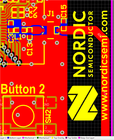
I understand the matching network to match the output impedance of the NRF52832 chip. I see in the reference design there is a trace for RF. When I open the NRF52-DK reference design I see that the entire antenna is there. My question is, how do I copy that trace to the reference design that I have? 

Trace I want to copy:
I want to copy it right there:
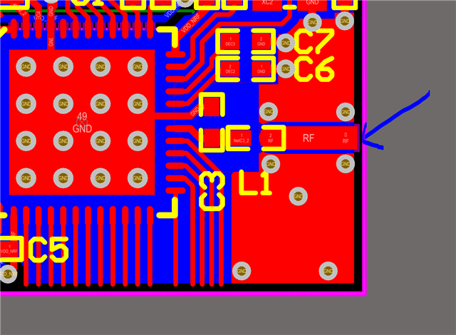
I'm thinking that this should work? Or is that absolutely crazy.

Thanks,

Rishi

Parents
  • Hi,


    The antenna trace can be connected directly to where you've pointed the blue arrow. This is also where you should position a tuning capacitor (like C15 in the DK). You can copy it as is, but I rather recommend that you just draw it so that it fits with your PCB, unless you have a large PCB with no obstructions/objects in that area. To keep the ground pour from surrounding it you should add a keep out, approximately as in the DK.


    Your design should then look like the DK design, if you remove J1 and fill the void by stretching the 'RF' trace towards the antenna.


    Best regards,

    Andreas

Reply
  • Hi,


    The antenna trace can be connected directly to where you've pointed the blue arrow. This is also where you should position a tuning capacitor (like C15 in the DK). You can copy it as is, but I rather recommend that you just draw it so that it fits with your PCB, unless you have a large PCB with no obstructions/objects in that area. To keep the ground pour from surrounding it you should add a keep out, approximately as in the DK.


    Your design should then look like the DK design, if you remove J1 and fill the void by stretching the 'RF' trace towards the antenna.


    Best regards,

    Andreas

Children
Related