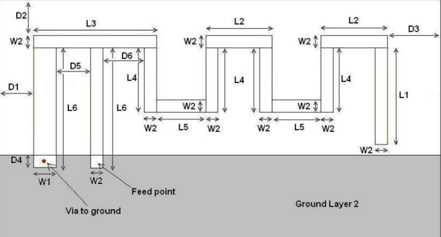
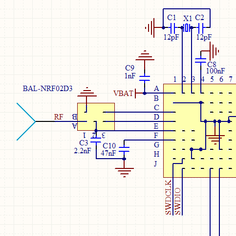
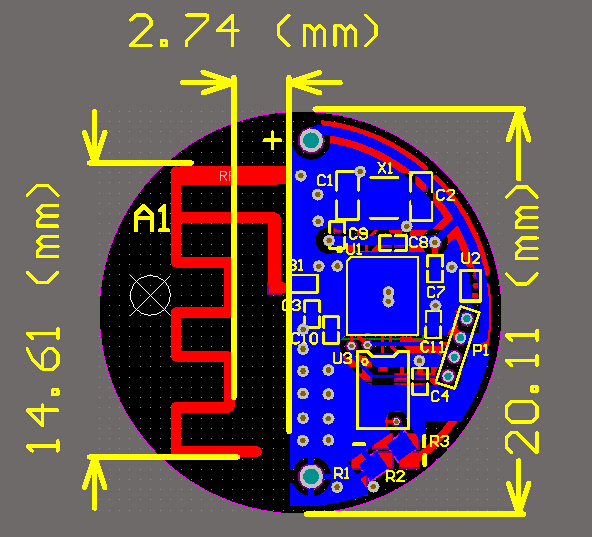
 Above is the "inverted—F" PCB antenna referenced.Below is the RF SCH and PCB layout,the PCB diameter is 20mm.Chip we use nrf51822 and bal-02d3.


 Can the antenna work well here? Is there any question?
 Above is the "inverted—F" PCB antenna referenced.Below is the RF SCH and PCB layout,the PCB diameter is 20mm.Chip we use nrf51822 and bal-02d3.


 Can the antenna work well here? Is there any question?
Hi,
I would always recommend adding an additional antenna tuner in form of a PI-network: en.wikipedia.org/.../Antenna_tuner
You're using an inverted F-antenna, which has a tap to ground (basically a shunt inductor), but this does not mean that it's guaranteed 50 ohm for this design.
I've posted an answer here why each different design must be tuned, regardless of antenna used.
Best regards, Håkon
Hi,
Your feed point is extended by the vertical pcb trace. It is not a 50 Ohm transmission line because there is no GND plane underneath. So in effect, you have a series inductance to your intended antenna feed point. Was that intentional?
May I ask what was the motivation to use PCB antenna? Have you considered a chip antenna?
I am also designing a board based on nrf51822 and I am pretty much confused about my design. I cannot set my mind on something that I would like to share with you.
Firstly, is using a balun like this any better than discrete matching network as given in the reference design ?
Secondly, is a chip antenna like this with the balun be viable and effective solution than inverted F antenna have already designed ?
Please have a look at this thread .