This post is older than 2 years and might not be relevant anymore
More Info: Consider searching for newer posts

Is there possible to get timer period shorter than 12us with nRF51 and SDK 14?

Is there possible to get timer period shorter than 12us with nRF51 and SDK 14?
"timer" example with PCA10040 works correct, but with PCA10028 not.
When set timer period lower than 12us it not corresponds to settings any more.

My code to start timer is following:

const nrf_drv_timer_t TIMER_LED = NRF_DRV_TIMER_INSTANCE(1);

void timer_led_event_handler(nrf_timer_event_t event_type, void* p_context)
{
    nrf_gpio_pin_toggle(LED_3);
}

void timer_start(void)
{
    nrf_drv_timer_config_t timer_cfg = NRF_DRV_TIMER_DEFAULT_CONFIG;
    uint32_t err_code = nrf_drv_timer_init(&TIMER_LED, &timer_cfg, timer_led_event_handler);
    APP_ERROR_CHECK(err_code);

    uint32_t time_ticks;
    time_ticks = nrf_drv_timer_us_to_ticks(&TIMER_LED, 5);

    nrf_drv_timer_extended_compare(
         &TIMER_LED, NRF_TIMER_CC_CHANNEL0, time_ticks, NRF_TIMER_SHORT_COMPARE0_CLEAR_MASK, true);

    nrf_drv_timer_enable(&TIMER_LED);

}

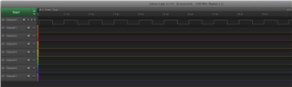
It gives following result

Period grater than 12us works correct (corresponds to plot).

  • Hello,

    There are no examples for the pca10028 in SDK14. The latest SDK that supports the nRF52 DK is SDK 12.3.0. Can you try to download the SDK12.3.0 (here) , and try one of the examples marked with "pca10028"?

    e.g. the example:

    SDK12.3.0\examples\peripheral\timer\pca10028\blank\...


    Best regards,

    Edvin

  • Hi Edvin,
    downloaded SDK 12.3.0, compared examples and they are identical. Going forward, compiled example for pca10028:
    nRF5_SDK_12.3.0_d7731ad\examples\peripheral\timer\pca10028\blank\armgcc
    Changed only nrf_drv_timer_ms_to_ticks -> nrf_drv_timer_us_to_ticks and timer handler to toggle single GPIO.
    Minimum period to achieve is 8.5us, even if set:
    time_ticks = nrf_drv_timer_us_to_ticks(&TIMER_LED, 1);

    Is possible to achieve higher frequency (I need period 5us)?

  • Hello,

    If you are looking for this short intervals, I would suggest that you use the PPI directly, and not through the timer module. You can also use this to toggle the pin without using the CPU, so it will not be affected by delays from this.

    /* Copyright (c) 2009 Nordic Semiconductor. All Rights Reserved.
     *
     * The information contained herein is property of Nordic Semiconductor ASA.
     * Terms and conditions of usage are described in detail in NORDIC
     * SEMICONDUCTOR STANDARD SOFTWARE LICENSE AGREEMENT.
     *
     * Licensees are granted free, non-transferable use of the information. NO
     * WARRANTY of ANY KIND is provided. This heading must NOT be removed from
     * the file.
     *
     */
    
    #include "nrf.h"
    #include <stdbool.h>
    #include <stdint.h>
    #include "bsp.h"
    #include "nrf_gpio.h"
    
    // Peripheral channel assignments
    #define PIN0_GPIOTE_CH      0
    #define PIN0_PPI_CH_A       0
    #define PIN0_PPI_CH_B       1
    #define PIN0_TIMER_CC_NUM   0
    
    
    // TIMER3 reload value. The frequency equals '16000000 / TIMER_RELOAD'
    #define TIMER_RELOAD        16
    // The timer CC register used to reset the timer. The timers on nRF51 have 4 CC registers.
    #define TIMER_RELOAD_CC_NUM 3
    // The pin toggles after TIMER_TOGGLE_VALUE number of ticks. (note that it is currently set up to also toggle after TIMER_RELOAD ticks.
    #define TIMER_TOGGLE_VALUE 8
    
    
    // This function initializes timer 0 with the following configuration:
    // 24-bit, base frequency 16 MHz, auto clear on COMPARE3 match (CC3 = TIMER_RELOAD)
    void timer_init()
    {
        NRF_TIMER0->BITMODE                 = TIMER_BITMODE_BITMODE_24Bit << TIMER_BITMODE_BITMODE_Pos;
        NRF_TIMER0->PRESCALER               = 0;
        NRF_TIMER0->SHORTS                  = TIMER_SHORTS_COMPARE0_CLEAR_Msk << TIMER_RELOAD_CC_NUM;   // restart timer after RELOAD_CC_NUM matches
        NRF_TIMER0->MODE                    = TIMER_MODE_MODE_Timer << TIMER_MODE_MODE_Pos;
        NRF_TIMER0->CC[TIMER_RELOAD_CC_NUM] = TIMER_RELOAD;    
        NRF_TIMER0->CC[PIN0_TIMER_CC_NUM]   = TIMER_TOGGLE_VALUE;
    }
    
    
    // Starts TIMER0
    void timer_start()
    {
        NRF_TIMER0->TASKS_START = 1;
    }
    
    
    // This function sets up TIMER0, the PPI and the GPIOTE modules to configure a single channel
    // Timer CC num, PPI channel nums and GPIOTE channel num is defined at the top of this file
    void PIN0_init(uint32_t pinselect)
    {  
        NRF_GPIOTE->CONFIG[PIN0_GPIOTE_CH] = GPIOTE_CONFIG_MODE_Task << GPIOTE_CONFIG_MODE_Pos | 
                                             GPIOTE_CONFIG_POLARITY_Toggle << GPIOTE_CONFIG_POLARITY_Pos | 
                                             pinselect << GPIOTE_CONFIG_PSEL_Pos | 
                                             GPIOTE_CONFIG_OUTINIT_High << GPIOTE_CONFIG_OUTINIT_Pos;
    
        NRF_PPI->CH[PIN0_PPI_CH_A].EEP = (uint32_t)&NRF_TIMER0->EVENTS_COMPARE[PIN0_TIMER_CC_NUM];      //first  compare after TIMER_TOGGLE_VALUE  (event)
        NRF_PPI->CH[PIN0_PPI_CH_A].TEP = (uint32_t)&NRF_GPIOTE->TASKS_OUT[PIN0_GPIOTE_CH];              //first  compare after TIMER_TOGGLE_VALUE  (task)
        NRF_PPI->CH[PIN0_PPI_CH_B].EEP = (uint32_t)&NRF_TIMER0->EVENTS_COMPARE[TIMER_RELOAD_CC_NUM];    //second compare after TIMER_RELOAD_CC_NUM (event)
        NRF_PPI->CH[PIN0_PPI_CH_B].TEP = (uint32_t)&NRF_GPIOTE->TASKS_OUT[PIN0_GPIOTE_CH];              //second compare after TIMER_RELOAD_CC_NUM (task)
        
        NRF_PPI->CHENSET               = (1 << PIN0_PPI_CH_A) | (1 << PIN0_PPI_CH_B);
    }
    
    
    int main(void)
    {
        // Initialize the timer
        timer_init();
        
        // Initialize pin toggle
        PIN0_init(LED_1);


        // Start the timer
        timer_start();
    
        while (true)
        {
            __WFI(); 
        }
    }
    

    Attached is a main file using the PPI directly. I modified from a PWM example for the nRF52, but it works with the nRF51 now. If you replace the main.c file in the SDK\examples\peripheral\timer example from SDK12.3.0, it should work just fine.

    Note that some of the comments might be from the original project, but I tried to change them to fit to the nRF51.


    The setup in this example toggles the LED1 every 0.5µs, as you can see here:

    If you need a period of 5µs, you should change:

    TIMER_RELOAD = 80

    TIMER_TOGGLE_VALUE = 40


    Alternatively, you can change the TIMER_RELOAD to be 40, and remove the PIN0_PPI_CH_B channel from PIN0_init();


    Play around with the example, and let me know if you have any issues with it.


    Best regards,

    Edvin

Related