Dear friend,
To use the Power Monitor for current profile measurement of nRF52832, I prepare the board by doing both of the steps described below:
(1) Short solder bridge SB12 (because i am using Power Monitor as external power supply for the DK) to bypass the protection diode which would otherwise give a voltage drop.
(2) Cut the PCB track shorting solder bridge SB9 to put P22 in series with the load.
(3) Add a jumper to P22. Should i do it?
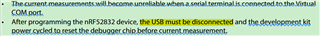
(3) After programming the nRF52832 device, the USB is disconnected and the development kit is reset.
The Power analyzer measurements are not be described in the nRF52832 Development Kit v1.1.x User Guide.
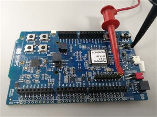
As shown in the figure below, are these steps right? I just want to measure the current of the nRF52832 SoC. If i want to split the power domains for the nRF52832 SoC and the rest of the board, what should i do?
thank u.