This post is older than 2 years and might not be relevant anymore
More Info: Consider searching for newer posts

UART Hardware Flow control does not seem to work - Connecting two nRF52840 dev boards together

Hi all,
I am trying to get my head around UART Flow control on Nordic nRF52. I cannot get it working...
I have two nRF52840 dev boards (PCA10056) that I connected between each others:

Board 1 (Sender)     Board 2 (Receiver)
P0.3 ------------------- P0.4
P0.4 ------------------- P0.3
P0.28 ------------------ P0.29
P0.29 ------------------ P0.28

I have not got UART logging enabled. I use a logic analyzer to see what is being sent.
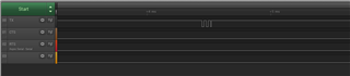
I noticed the Receiver does not block while waiting to receive.

Here is the source code:

The same source code is build with `-DSENDER=1` for the sender and no declaration for the receiver.
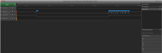
When the receiver is switched off, I can see my packet being sent from the sender.

#include <stdbool.h>
#include <stdint.h>
#include <stdio.h>
#include "app_uart.h"
#include "app_error.h"
#include "nrf_delay.h"
#include "nrf.h"
#include "bsp.h"
#if defined (UART_PRESENT)
#include "nrf_uart.h"
#endif
#if defined (UARTE_PRESENT)
#include "nrf_uarte.h"
#endif
#include "nrf_drv_uart.h"

#include "nrf_gpio.h"

#include "nrf_log.h"
#include "nrf_log_ctrl.h"
#include "nrf_log_default_backends.h"

uint8_t command[] = { 7, 198, 4, 8, 255, 159, 1, 253, 136 };

#define UART_RX_PIN   3
#define UART_TX_PIN   4
#define UART_RTS_PIN  28
#define UART_CTS_PIN  29

#define SUPPORT_HARDWARE_FLOW_CONTROL

uint8_t response[32];

/**
 * @brief Function for main application entry.
 */
int main(void)
{
    uint32_t err_code;
    ret_code_t ret;

    APP_ERROR_CHECK(NRF_LOG_INIT(NULL));
    NRF_LOG_DEFAULT_BACKENDS_INIT();

    /* Configure board. */
    bsp_board_leds_init();

#if SENDER
    NRF_LOG_ERROR("Sender");
#else
    NRF_LOG_ERROR("Receiver");
#endif

    static nrf_drv_uart_t app_uart_inst = NRF_DRV_UART_INSTANCE(0);

    nrf_drv_uart_config_t uart_config = NRF_DRV_UART_DEFAULT_CONFIG;
    uart_config.baudrate = 0x00275000UL; // 9600
#ifdef SUPPORT_HARDWARE_FLOW_CONTROL
    uart_config.hwfc = 1;
#else
    uart_config.hwfc = 0;
#endif
    uart_config.pselrxd = UART_RX_PIN;
    uart_config.pseltxd = UART_TX_PIN;
#ifdef SUPPORT_HARDWARE_FLOW_CONTROL
    uart_config.pselrts = UART_RTS_PIN;
    uart_config.pselcts = UART_CTS_PIN;
#endif
    uart_config.parity = 0; // No Parity
    uart_config.use_easy_dma = true;

    err_code = nrf_drv_uart_init(&app_uart_inst, &uart_config, NULL);
    if (err_code != NRF_SUCCESS) {
        NRF_LOG_ERROR("Error1 ErrCode:0x%x\n", err_code);
        while(1);
    }

    nrf_drv_uart_rx_enable(&app_uart_inst);

#if SENDER
    ret =  nrf_drv_uart_tx(&app_uart_inst, command, sizeof(command));
#else
    ret = nrf_drv_uart_rx(&app_uart_inst, response, sizeof(command));
#endif

    if (NRF_ERROR_BUSY == ret)
    {
        bsp_board_led_invert(1);
        NRF_LOG_ERROR("Error2");
    }
    else if (ret != NRF_SUCCESS)
    {
        bsp_board_led_invert(2);
        NRF_LOG_ERROR("Error3 ret:0x%x (error_reg:0x%02x)", ret, nrf_drv_uart_errorsrc_get(&app_uart_inst));
    }
    else
    {
        bsp_board_led_invert(0);
        bsp_board_led_invert(3);

#ifndef SENDER
        NRF_LOG_ERROR("Received: %02x%02x%02x%02x", response[0], response[1], response[2], response[3]);
#endif
    }

    while (true)
    {
    // Do nothing.
    }
}


/** @} */

  • Why do you need the "#if SENDER ... #else... #endif" when you have already done the physical cross wiring between the two units?

  • Thanks Matt, you are right. By reversing the wire and the pinmux it did not help...

    I have made some progress (and I also added some logging using the other UART). I edited the code with the latest version

    Now, the receiver complains:

    Error3 ret:0x3 (error_reg:0x4)

    From the doc (http://infocenter.nordicsemi.com/topic/com.nordic.infocenter.nrf52840.ps/uarte.html?cp=2_0_0_33_9_4#register.ERRORSRC), it means it is a FRAMING error (A valid stop bit is not detected on the serial data input after all bits in a character have been received.).

    I am guessing I forgot something when sending my command. But I cannot find what is missing from the sender...

  • Actually the logic analyzer see the framing error. But I cannot find the error in my code.

  • Have you tested any of the uart examples, either SDK\examples\peripheral\uart or SDK\examples\peripheral\serial?

    Do you see the same behavior there?


    Best regards,
    Edvin

  • I have just tried with a slightly modified version of SDK\examples\peripheral\uart to be used between two nRF52840 DK boards with HW flow control.

    The boards are connected as follow:

    Board 1 (Sender)     Board 2 (Receiver)
    P0.3 (TX)  ------------------- P0.3 (RX)
    P0.4  (RTS) ------------------ P0.4 (CTS)
    P0.28 (CTS) ------------------ P0.28 (RTS)


    I changed the code as follow (I am using nRF5_SDK_14.2.0):

    --- a/nRF5_SDK_14.2.0_17b948a/examples/peripheral/uart/main.c
    +++ b/../../../main.c
    @@ -62,6 +62,17 @@
     #include "nrf_uarte.h"
     #endif
     
    +#ifdef SENDER
    +#define UART_RX_PIN_NUMBER  8  /* Received characters from the terminal */
    +#define UART_TX_PIN_NUMBER  3  /* Send it to P0.3 */
    +#define UART_CTS_PIN_NUMBER 4  /* CTS: P0.4 */
    +#define UART_RTS_PIN_NUMBER 28 /* RTS: P0.28 */
    +#else
    +#define UART_RX_PIN_NUMBER  3  /* Receive characters from Sender */
    +#define UART_TX_PIN_NUMBER  6  /* Send characters to the terminal */
    +#define UART_CTS_PIN_NUMBER 28 /* RTS: P0.28 */
    +#define UART_RTS_PIN_NUMBER 4  /* RTS: P0.4 */
    +#endif
     
     //#define ENABLE_LOOPBACK_TEST  /**< if defined, then this example will be a loopback test, which means that TX should be connected to RX to get data loopback. */
     
    @@ -126,9 +137,10 @@ static void uart_loopback_test()
     }
     #else
     /* When UART is used for communication with the host do not use flow control.*/
    -#define UART_HWFC APP_UART_FLOW_CONTROL_DISABLED
    +//#define UART_HWFC APP_UART_FLOW_CONTROL_ENABLED
     #endif
     
     /**
      * @brief Function for main application entry.
    @@ -141,10 +153,10 @@ int main(void)
     
         const app_uart_comm_params_t comm_params =
           {
    -          RX_PIN_NUMBER,
    -          TX_PIN_NUMBER,
    -          RTS_PIN_NUMBER,
    -          CTS_PIN_NUMBER,
    +          UART_RX_PIN_NUMBER,
    +         UART_TX_PIN_NUMBER,
    +         UART_RTS_PIN_NUMBER,
    +         UART_CTS_PIN_NUMBER,
               UART_HWFC,
               false,
               NRF_UART_BAUDRATE_115200
    @@ -159,6 +171,12 @@ int main(void)

    I cannot see the RTS/CTS signal change. I was expecting to see changes with RTS and CTS signals.

Related