This post is older than 2 years and might not be relevant anymore
More Info: Consider searching for newer posts

Electrical schematic of IO buffers?

I wonder if Nordic reveals electrical schematic of IO buffers?

I have taken some current consumption measurements recently and I have realized that setting a pin as input without pulling can also greatly increase current consumption  under some conditions.

Look at below simple part of the circuit.

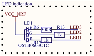
LED* are directly connected to nRF GPIO port.

RGB leds are sensitive to light and when my device is illuminated by the sun I can realize increase in current consumption (about 300 uA) when LED* are set as INPUT no pulling (I thought this is high impedance state, isn't it?). However when I set LED* as OUTPUT and drive them high there is no increase in current consumption in similar conditions, what is quite obvious cause there is no electric potential difference.

It would be nice if Nordic could share more detailed electrical schematic of IO buffers.

Parents
  • Hi, we don't have detailed electrical schematic of IO buffers, but I expect the case here is that the input is floating without a defined level. In such case you can have excessive current due to a current path may occur internally between VDD and GND, this will not damage the part, but can cause current of several hundreds of uA. This is a common problem with floating inputs in general, typical workarounds are either set as output, use pull up or down, or disconnect the input internally when not in use. There is an application note from TI that also describe more details here.

Reply
  • Hi, we don't have detailed electrical schematic of IO buffers, but I expect the case here is that the input is floating without a defined level. In such case you can have excessive current due to a current path may occur internally between VDD and GND, this will not damage the part, but can cause current of several hundreds of uA. This is a common problem with floating inputs in general, typical workarounds are either set as output, use pull up or down, or disconnect the input internally when not in use. There is an application note from TI that also describe more details here.

Children
No Data
Related