Beware that this post is related to an SDK in maintenance mode
More Info: Consider nRF Connect SDK for new designs
This post is older than 2 years and might not be relevant anymore
More Info: Consider searching for newer posts

Unable to interface nrf51822 with LIS3DH (accelerometer) using SPI being nrf as master

Hi, 

I tried interfacing LIS3Dh using SPI, I used the SPI example to start with, when I didn't get the desired result, I look numerous question on the forum and tried to modify the code but it does not seem to be working.

I am simply trying to read WHO_AM_I register/or any other register, I am getting FF always, 

the sensor is embedded on PCB with following configurations: 

Configurations:

LIS3DH nrf 51822 pin  sdk_config.h 
SCK 9 SPI_SCK_PIN 9
SDI 10 SPI_MOSI_PIN 10
CS 12 SPI_SS_PIN 12
SDO 7 SPI_MISO_PIN 11

Below code is trying to read who_am_i ( 0x0F) 

#define SPI_INSTANCE  0 /**< SPI instance index. */
static const nrf_drv_spi_t spi = NRF_DRV_SPI_INSTANCE(SPI_INSTANCE);  /**< SPI instance. */
static volatile bool spi_xfer_done;  /**< Flag used to indicate that SPI instance completed the transfer. */

#define TEST_STRING "Nordic"
static uint8_t       m_tx_buf[]={0x0F};           /**< TX buffer. */
static uint8_t       m_rx_buf[]={0x00, 0x00,0x00, 0x00,0x00};    /**< RX buffer. */
//static const uint8_t m_length = sizeof(m_rx_buf);        /**< Transfer length. */

/**
 * @brief SPI user event handler.
 * @param event
 */
void spi_event_handler(nrf_drv_spi_evt_t const * p_event)
{
    spi_xfer_done = true;
    SEGGER_RTT_printf(0,"Transfer completed.\r\n");
    if (1 != 0)
    {
        SEGGER_RTT_printf(0," Received: \r\n");
        NRF_LOG_HEXDUMP_INFO(m_rx_buf, strlen((const char *)m_rx_buf));
        SEGGER_RTT_printf(0, "value: %u \r\n", *m_rx_buf);
        bsp_board_led_invert(BSP_BOARD_LED_1);
    }
}

int main(void)
{
    bsp_board_leds_init();

    APP_ERROR_CHECK(NRF_LOG_INIT(NULL));

    SEGGER_RTT_printf(0,"SPI example\r\n");

   nrf_drv_spi_config_t spi_config = NRF_DRV_SPI_DEFAULT_CONFIG;
	spi_config.ss_pin   = SPI_SS_PIN;
	spi_config.miso_pin = SPI_MISO_PIN;
	spi_config.mosi_pin = SPI_MOSI_PIN;
	spi_config.sck_pin  = SPI_SCK_PIN;
	spi_config.frequency= NRF_DRV_SPI_FREQ_8M;
	spi_config.mode= NRF_DRV_SPI_MODE_2;
        
	APP_ERROR_CHECK(nrf_drv_spi_init(&spi, &spi_config, spi_event_handler));
        
       
        uint8_t sizerx = 2;
        spi_xfer_done = false;
        
        APP_ERROR_CHECK(nrf_drv_spi_transfer(&spi, m_tx_buf, 1, m_rx_buf, sizerx));
        while (!spi_xfer_done){
	  __WFE();
        }

        if(sizerx!=0)
        {
            SEGGER_RTT_printf(0,"Received[0]: %x %x %x %x %x \n\r",m_rx_buf[0],m_rx_buf[1],m_rx_buf[2],m_rx_buf[3],m_rx_buf[4]);
        }else{
            SEGGER_RTT_printf(0,"no value return from \r\n");
        }
      
      SEGGER_RTT_printf(0,"miso-> %u \r\n", nrf_gpio_pin_out_read(11));
      SEGGER_RTT_printf(0,"mosi-> %u \r\n", nrf_gpio_pin_out_read(10));
      SEGGER_RTT_printf(0,"ss-> %u \r\n", nrf_gpio_pin_out_read(12));
                     
}

log output ( in every case I am getting FF value in rx_buff ) 
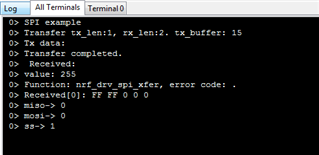
SDK Used: 12.2

using JLink to transfer the via SWO

I have tried with different modes and frequencies also but no luck. 

Please help.

  • Hi,

    Have you checked the SPI bus with a logic analyzer, to see if anything is actually transmitted/received? 

    Best regards,
    Jørgen

  • No, I dont have logic analyzer 

    Is there any other way to check ?

  • You have at least two problems: you might try SPI_MODE_0 instead of MODE_2, as that works correctly with the similar part LIS2DH12. Also if this is the first time you have used SPI, it's not obvious that to receive (say) 5 bytes that you actually have to transmit 5 bytes as the transmit provides the clock required for the receive. In the case above only 1 byte is transmitted, so increase that to 5

        spi_config.ss_pin    = ACC_CS_PIN;
        spi_config.miso_pin  = ACC_MISO_PIN;
        spi_config.mosi_pin  = ACC_MOSI_PIN;
        spi_config.sck_pin   = ACC_SCK_PIN;
        spi_config.frequency = NRF_SPI_FREQ_8M;
        spi_config.bit_order = NRF_DRV_SPI_BIT_ORDER_MSB_FIRST;
        spi_config.mode      = NRF_DRV_SPI_MODE_0;
        APP_ERROR_CHECK(nrf_drv_spi_init(&mAccSpiInstance, &spi_config, acc_spi_event_handler, NULL));
    
    static uint8_t m_tx_buf[]={0x0F, 0x00, 0x00, 0x00, 0x00}; /**< TX buffer. */
    static uint8_t m_rx_buf[]={0x00, 0x00, 0x00, 0x00, 0x00}; /**< RX buffer. */
    static const uint8_t m_length = sizeof(m_rx_buf);       /**< Transfer length. */
    
    // Ensure transmit and receive buffers are identical lengths
    #include "nrf_drv_common.h";
    STATIC_ASSERT(sizeof(m_rx_buf) == sizeof(m_tx_buf));
    

    And now specify correct lengths:

    // Ensure transmit and receive buffers are identical lengths
    #include "nrf_drv_common.h";
    
    // 2 bytes each or whatever ..
    uint8_t sizerx = 2, sizerx = 2;
    
    STATIC_ASSERT(sizetx == sizerx);
    
    APP_ERROR_CHECK(nrf_drv_spi_transfer(&spi, m_tx_buf, sizetx, m_rx_buf, sizerx));
    

  • Hi,

    Thanks for guiding. yeah, I am implementing SPI for first time, I increased the size of tx_buff to 5, and before sending I specify the correct length

     uint8_t rx_length = 1;        /**< Transfer length. */
            uint8_t tx_length = 1;
            
            spi_xfer_done = false;
            //STATIC_ASSERT(tx_length == rx_length);
            APP_ERROR_CHECK(nrf_drv_spi_transfer(&spi, m_tx_buf, tx_length, m_rx_buf, rx_length));
            while (!spi_xfer_done){
    	  __WFE();
            }

    static uint8_t m_tx_buf[]={0x0F, 0x00, 0x00, 0x00, 0x00}; /**< TX buffer. */
    static uint8_t m_rx_buf[]={0x00, 0x00, 0x00, 0x00, 0x00}; /**< RX buffer. */

    I kept the mode=2 because in datasheet of sensor is says " Those lines are driven at the falling edge of SPC and should be captured at the rising edge of SPC". 

    Output is still FF only. 

    Thank you for quick reply :) 

  • The SPI can't return the id you require using your code since the LIS doesn't know what the command is until after the 8-bit tx transfer is complete. If sending an 8-bit command that didn't require a response then a length of 1 byte transfer is fine, but you want the ID response so therefore you require a 2-byte transfer: 1st tx byte is request, 2nd a dummy 0. 1st Rx byte a dummy, 2nd a response to the Tx command request. In general the Rx stream is always 1-byte behind the tx stream since the first tx byte instructs the LIS what to put in the response.

    I would stick with Mode 0 as that works .. also I would recommend finding the LIS in the examples, eg: look in Thingy SDK v2.1.0\include\frivers which can be downloaded from Nordic

    /**@brief Read and verify accelerometer ID.
     */
    static ret_code_t lis3dh_verify_id(void)
    {
        ret_code_t  err_code;
        uint8_t     reg_val;
    
        err_code = lis3dh_read_regs(WHO_AM_I, &reg_val);
        RETURN_IF_ERROR(err_code);
    
        return (reg_val == I_AM_LIS3DH);
    }
    

Related