This post is older than 2 years and might not be relevant anymore
More Info: Consider searching for newer posts

Debug Connector

Hi,

I have nrf52840 DK, I am unable to find details of which debug pin connected connected to respective controller pin.

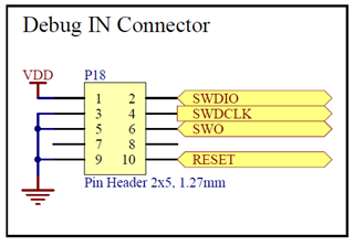
basically dev kit has 10pin "Debug input" I want to know which controller pin goes to which connector.

Parents
  • You can check the nrf52840 pdk reference layout at the bottom of this link. Unzip the file & open the PCA10056_Schematic_And_PCB pdf file located in the Schematic_Layout pdf files folder. You might need to shorten the name of the downloaded zip to be able to extract the file. Also, try unzipping the file as close to the C drive as possible (e.g. C:\NordicSemi\52840.zip).

    On sheet six, you can see this image:

    As can be seen, pin 1 connects to VDD, pins 3,5 & 9 are connected to ground & pins 7 & 8 are left unconnected.

    Pin 2: SWDIO

    Pin 4: SWDCLK

    Pin 6: SWO

    Pin 10: RESET

    From there, you can take a look at sheet 2, where you should be able to figure out how each of the pins connects to the 52840 SoC.


Reply
  • You can check the nrf52840 pdk reference layout at the bottom of this link. Unzip the file & open the PCA10056_Schematic_And_PCB pdf file located in the Schematic_Layout pdf files folder. You might need to shorten the name of the downloaded zip to be able to extract the file. Also, try unzipping the file as close to the C drive as possible (e.g. C:\NordicSemi\52840.zip).

    On sheet six, you can see this image:

    As can be seen, pin 1 connects to VDD, pins 3,5 & 9 are connected to ground & pins 7 & 8 are left unconnected.

    Pin 2: SWDIO

    Pin 4: SWDCLK

    Pin 6: SWO

    Pin 10: RESET

    From there, you can take a look at sheet 2, where you should be able to figure out how each of the pins connects to the 52840 SoC.


Children
Related