This post is older than 2 years and might not be relevant anymore
More Info: Consider searching for newer posts

nRF52832 IO problem

Hello!

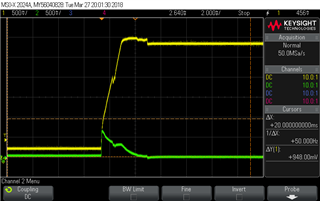
We have nRF52832 chip on our product and we have some problem with one of its IOs.. We configured P0.16 as RX of UART, And when we run it we see this behavior of this IO:
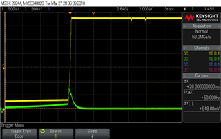
VCC (yellow) vs P0.16 (green) that configured as UART_RX

Here we see that with rising of VCC (yellow signal) IO (green) rising to almost 1V when it supposed to still at 0V. Important note: we disable and enable VCC fast here so we see that before rising of VCC it don't have 0V. This behaviour is very problematic to our system. Because we have power supply sensitive sensor that connected to this UART. This spike of voltage damage sensor that connected to this IO.

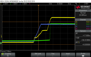
We tried to load to evaluation board same version of SW on nRF52832 and we got next result:
We see that also here we have the problematic spike.

When we erased the evaluation board - we got the same result.

Is this IO known as problematic?

Thank you

Parents
  • It seems very curious that the sensor is getting damaged due to a spike that's <1V for just a small period of time.  

    For a typical UART configuration, the 'inactive' state will be HI and a transmission starts with the transition from HI-LOW, indicating the start bit when a byte is arriving.  Even after the little 'bump' on power-up (which seems very reasonable, it takes a small amount of time for the processor to get control of the IO), I would expect that the UART RX line would get pulled hi, especially with the 100k pull-up that you mention.  Something is strange here.    

    You also mention that your sensor is powered off of 9V.  I assume you're using some sort of level-shifter to make sure that any signals sent to the NRF are down at a safe voltage level, correct?

    Cheers,

    Roger

  • Yeah, it is also very strange for us also..

    The sensor powered by 9V, but it have on-sensor buck converter that convert 9V to 3.3V to power-up the on-sensor microprocessor MSP430G2744. This on-sensor microprocessor is the part that communicate via UART with nRF. The 9V used only for accelerometer that placed on the sensor.

    As I write this I am thinking about something - is this possible that on-sensor buck output come lately after the signals from nRF?.. Need to check this.

  • There will be some small start-up time for the buck but it is probably very minimal.  It sounds like your timing is very critical between the NRF and your sensor.  Perhaps it makes sense to wait for a delay (a few mS) after startup, then have your NRF pull the reset line of the MSP430, and then start your communication.  This way you can guarantee that everything is fully powered up before you try to pass data between the micros.

    Even with that said, I still do not understand why your UART RX line is low even when there is a 100k pull-up.  If that condition is still there even after everything has been powered up and configured, there is a hardware problem or a configuration problem somewhere and that issue needs to be resolved before going any further.

  • I did the test and it seems ok:

    Yellow is 9V, green is nRF 3.3V and blue is on-sensor buck 3.3V

  • Even with that said, I still do not understand why your UART RX line is low even when there is a 100k pull-up.  If that condition is still there even after everything has been powered up and configured, there is a hardware problem or a configuration problem somewhere and that issue needs to be resolved before going any further

    At screenshots at first topic there are still no pull-up so here the IO start at low. We tried pull-up 100k and it worked as expected - at start-up it pulled to 3.3V as needed.

  • If we back up a little bit, why did you get to the conclusion that the small spike on power-up of the NRF damaged your MSP430?

    Have you tried putting your scope on the TX/RX lines of the UART once everything is powered up, in order to verify that there is serial traffic from whichever micro is supposed to start talking first?

Reply Children
  • Looks like a classic phantom power issue, which I mention earlier in this thread, given the MSP430 powers up long before the nRF SoC. If there are other devices attached (host MCU or external serial port to PC etc) care is required to ensure no port pins are driving into the nRF52832 SoC during a power-down period. In a simple system with a host MCU typically a UART Rx, Tx and the nRF52832 SoC RST pins will be connected between host MCU and nRF52832 SoC. In that simple case either Rx or Reset pins will phantom power the entire nRF52832 SoC if they are left driven high while nRF52832 SoC power is removed. This is perhaps not unexpected if we assume dual internal schottky diode protection (a clamp diode to both GND and VCC) instead of single internal schottky diode (to GND with low breakdown voltage). This means that to power-down the nRF52832 SoC the MCU code must first drive both UART RX and BLE RST pins low, otherwise the supply of (say) 3 volts only drops to 2 volts or so when the supply is switched off and the nRF52832 SoCtherefore does not reset.
    In a similar manner, connecting a typical FTDI USB serial port to the nRF52832 SoC can unexpectedly phantom power the part, and stop it correctly resetting or powering down unless the FTDI is first removed. This can cause confusing and unexpected behavior. There is an excellent Dialog publication Training_07_DA1458x_prototype_bring_up_guide _Training_07_DA1458x_prototype_bring_up_guide -v1. 2I 2I_ which actually touches on this without mentioning why:
    It is recommended that P0_4 and P0_5 are made available for UART communication during production test and board bring-up. Note that, if the two pins are also used as interface to an external MCU, that this MCU will need to be able to high-Z the pin connected to P0_5
    The reason is that resetting the test board doesn't work correctly unless drive to the Rx pin is first removed, including drive from any connected FTDI USB serial port or driving low or floating any connected host MCU.

    The MSP430 port pin may not survice powering up the entire nRF Soc; if you can't stop the MSP430 line driving to the nRF then perhaps add a series current-limiting resistor.

  • I touch with oscilloscope the TX pin on MSP430 package and see that it no transmit anymore when it damaged. 

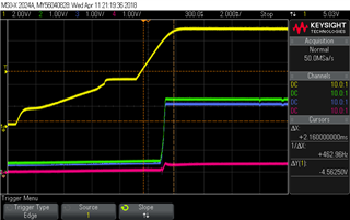
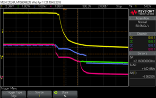
    Here the screenshots of UART IOs and supplies that we already did:

    This is power-up (with 100k pull-up resistor on TX):

    Yellow - 9V, green - 3.3V, pink - RX, blue - TX (IO that get damaged)

    This is power-down:

    And yes, I put scope on IO of MSP and see transmission when the chip works ok. And don't transmit data when it no.

  • Looks like a classic phantom power issue, which I mention earlier in this thread, given the MSP430 powers up long before the nRF SoC. If there are other devices attached (host MCU or external serial port to PC etc) care is required to ensure no port pins are driving into the nRF52832 SoC during a power-down period. In a simple system with a host MCU typically a UART Rx, Tx and the nRF52832 SoC RST pins will be connected between host MCU and nRF52832 SoC. In that simple case either Rx or Reset pins will phantom power the entire nRF52832 SoC if they are left driven high while nRF52832 SoC power is removed. This is perhaps not unexpected if we assume dual internal schottky diode protection (a clamp diode to both GND and VCC) instead of single internal schottky diode (to GND with low breakdown voltage). This means that to power-down the nRF52832 SoC the MCU code must first drive both UART RX and BLE RST pins low, otherwise the supply of (say) 3 volts only drops to 2 volts or so when the supply is switched off and the nRF52832 SoCtherefore does not reset.
    In a similar manner, connecting a typical FTDI USB serial port to the nRF52832 SoC can unexpectedly phantom power the part, and stop it correctly resetting or powering down unless the FTDI is first removed. This can cause confusing and unexpected behavior. There is an excellent Dialog publication Training_07_DA1458x_prototype_bring_up_guide _Training_07_DA1458x_prototype_bring_up_guide -v1. 2I 2I_ which actually touches on this without mentioning why:
    It is recommended that P0_4 and P0_5 are made available for UART communication during production test and board bring-up. Note that, if the two pins are also used as interface to an external MCU, that this MCU will need to be able to high-Z the pin connected to P0_5
    The reason is that resetting the test board doesn't work correctly unless drive to the Rx pin is first removed, including drive from any connected FTDI USB serial port or driving low or floating any connected host MCU.

    We now making tests to put series current-limit resistor. With 51 ohm it still got damaged, and with 102 ohm it seems to survive, but we will test more. We are running power-on/power-off tests that power on and off the board every 8 seconds, For now board with sensor and series resitors run 1 week and looks good. When at the past it was damaged after 1-2 days. And with 51 ohm it run 4 days.

    So maybe this is really the solution that we need

    Thank you

  • I would suggest rather more than 102 ohm; assume worst-case 3.3 volts @ (say) 10mA limit indicates 330 ohms minimum. A more robust alternative might be to use something like SN74LV1T34 Single Power Supply Single Buffer GATE CMOS Logic Level Shifter. The resistor solution can limit maximum baud rate due to distributed capacitance, although I would imagine you are not above 115,200 in which case 330 ohm is fine.

  • We run UART at 230400 baud rate.. So as you say - we need to use the buffer?

Related