This post is older than 2 years and might not be relevant anymore
More Info: Consider searching for newer posts

NRF8001 dc/dc converter enabled schematic

Hello,

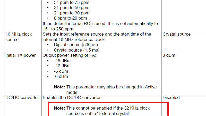
I attached the schematic found in the manual for NRF8001, in the case of DC/DC converter enabled. It shows that an external 32.768KHZ crystal is used, while in the table(also attached) shows that in case the DC/Dc converter to be enabled the external crystal cannot be used.

Please clarify if i have to add the external crystal in case i want to use the DC/Dc converter.

Thanks

schematic.png

table.png

Parents
  • You should not have both a crystal and the DC/DC components on your board. This design is done like that just to show how both should be done in one drawing.

    If you want to use the DC/DC, you should use another 32 kHz clock source than a crystal, and if you want to use a crystal, there is no reason to mount the DC/DC components.

Reply
  • You should not have both a crystal and the DC/DC components on your board. This design is done like that just to show how both should be done in one drawing.

    If you want to use the DC/DC, you should use another 32 kHz clock source than a crystal, and if you want to use a crystal, there is no reason to mount the DC/DC components.

Children
No Data