This post is older than 2 years and might not be relevant anymore
More Info: Consider searching for newer posts

nRF52832 RTC timing is inaccurate

Hi,    
    Now I am using nRF52382 to make a product which needs a accurate one second timing. Then I use the project "nRF5_SDK_15.0.0_a53641a\examples\peripheral\rtc" and "nRF5_SDK_15.0.0_a53641a\examples\peripheral\timer" to make examples for timing.  They are all set for one millisecond interruption, and I find the timing is inaccurate. More importantly,  different chips which are downloaded the same program have different deviation time.    
 
                     For example, there are two nRF53832 chips which are set one second timing by the project "nRF5_SDK_15.0.0_a53641a\examples\peripheral\timer". But they have different timing actually. As shown below.
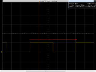
"ChipA" Timing one second but it is actually 1.003s
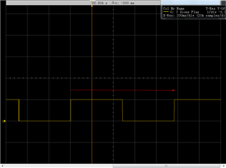
"ChipB" Timing one second but it is actually0.992s
     How can I make a accurate timing or make sure every chip has the same timing result?

Best Regards
Parents
  • This seems to be a running gag on this website that no one knows you can't do millisecond ISR's with accuracy.  This is true of any computer not just Nordic.

    The reason of course is that ISR's have priority, get queued, and take random amounts of time to service depending on where the process came from and what it had to do to finish your ISR, Add all this up and you get voila!!! random latency.

    If you want an accurate second timer, just run the RTC through a 14bit counter.  These are already hardwired on the board as RTC0, RTC1, RTC2.

    Then if you are compelled to handle stuff in code, generate 1 second ISR's and the latency will be minimized. 

    Ideally, if one cared about accuracy they would keep all of it in hardware and just poll the registers async in the code.  Then there is no latency.

    Also, be aware the the absolute error is tied to your external RTC crystal.  Some people buy terrible crystals or choose to work off of LF_RC which is a bad idea.

  • Thank you for your reply. Actually I run the program on the nRF development board but not website, so there is irelevant to computer. And the mcu just uses internal crystal. I get the timing diagram by JLink Scope. 

    Here is the program. I use Timer0 to make a  500ms  interruption.  I still find the timing is inaccurate by the J-Link scope.

    I also try Timer1 and  RTC0 but they have the same problem.

    uint8_t J_Scope_Flag = 0;
    
    const nrf_drv_timer_t TIMER_LED = NRF_DRV_TIMER_INSTANCE(0);
    
    /**
     * @brief Handler for timer events.
     */
    void timer_led_event_handler(nrf_timer_event_t event_type, void* p_context)
    {
        static uint32_t i;
    		static uint8_t state = 0;
        uint32_t led_to_invert = ((i++) % LEDS_NUMBER);
    
        switch (event_type)
        {
            case NRF_TIMER_EVENT_COMPARE0:
                bsp_board_led_invert(led_to_invert);
    				
    						if(state)
    						{
    							J_Scope_Flag = 1;
    							state = 0;
    						}else{
    							J_Scope_Flag = 0;
    							state = 1;
    						}
                break;
    
            default:
                //Do nothing.
                break;
        }
    }
    
    
    /**
     * @brief Function for main application entry.
     */
    int main(void)
    {
        uint32_t time_ms = 500; //Time(in miliseconds) between consecutive compare events.
        uint32_t time_ticks;
        uint32_t err_code = NRF_SUCCESS;
    
        //Configure all leds on board.
        bsp_board_init(BSP_INIT_LEDS);
    
        //Configure TIMER_LED for generating simple light effect - leds on board will invert his state one after the other.
        nrf_drv_timer_config_t timer_cfg = NRF_DRV_TIMER_DEFAULT_CONFIG;
        err_code = nrf_drv_timer_init(&TIMER_LED, &timer_cfg, timer_led_event_handler);
        APP_ERROR_CHECK(err_code);
    
        time_ticks = nrf_drv_timer_ms_to_ticks(&TIMER_LED, time_ms);
    
        nrf_drv_timer_extended_compare(
             &TIMER_LED, NRF_TIMER_CC_CHANNEL0, time_ticks, NRF_TIMER_SHORT_COMPARE0_CLEAR_MASK, true);
    
        nrf_drv_timer_enable(&TIMER_LED);
    
        while (1)
        {
            __WFI();
        }
    }

Reply
  • Thank you for your reply. Actually I run the program on the nRF development board but not website, so there is irelevant to computer. And the mcu just uses internal crystal. I get the timing diagram by JLink Scope. 

    Here is the program. I use Timer0 to make a  500ms  interruption.  I still find the timing is inaccurate by the J-Link scope.

    I also try Timer1 and  RTC0 but they have the same problem.

    uint8_t J_Scope_Flag = 0;
    
    const nrf_drv_timer_t TIMER_LED = NRF_DRV_TIMER_INSTANCE(0);
    
    /**
     * @brief Handler for timer events.
     */
    void timer_led_event_handler(nrf_timer_event_t event_type, void* p_context)
    {
        static uint32_t i;
    		static uint8_t state = 0;
        uint32_t led_to_invert = ((i++) % LEDS_NUMBER);
    
        switch (event_type)
        {
            case NRF_TIMER_EVENT_COMPARE0:
                bsp_board_led_invert(led_to_invert);
    				
    						if(state)
    						{
    							J_Scope_Flag = 1;
    							state = 0;
    						}else{
    							J_Scope_Flag = 0;
    							state = 1;
    						}
                break;
    
            default:
                //Do nothing.
                break;
        }
    }
    
    
    /**
     * @brief Function for main application entry.
     */
    int main(void)
    {
        uint32_t time_ms = 500; //Time(in miliseconds) between consecutive compare events.
        uint32_t time_ticks;
        uint32_t err_code = NRF_SUCCESS;
    
        //Configure all leds on board.
        bsp_board_init(BSP_INIT_LEDS);
    
        //Configure TIMER_LED for generating simple light effect - leds on board will invert his state one after the other.
        nrf_drv_timer_config_t timer_cfg = NRF_DRV_TIMER_DEFAULT_CONFIG;
        err_code = nrf_drv_timer_init(&TIMER_LED, &timer_cfg, timer_led_event_handler);
        APP_ERROR_CHECK(err_code);
    
        time_ticks = nrf_drv_timer_ms_to_ticks(&TIMER_LED, time_ms);
    
        nrf_drv_timer_extended_compare(
             &TIMER_LED, NRF_TIMER_CC_CHANNEL0, time_ticks, NRF_TIMER_SHORT_COMPARE0_CLEAR_MASK, true);
    
        nrf_drv_timer_enable(&TIMER_LED);
    
        while (1)
        {
            __WFI();
        }
    }

Children
  • well for a start the TIMERs use the HF clock and in that code you're not starting it explicitly which means youj're using the RC HF clock which is going to have very random accuracy. Explicitly start the HF clock, although your power consumption is going to be terrible like that. 

    Don't know what you did for RTC0 however if  you didn't have or didn't start the 32.768kHz crystal in that case either you'll have been running of a random RC source as well. 

    If you use an accurate crystal source, ensure it's running and ensure your count is not affected by interrupt latency (by using the SHORTs as in the code above), your timings will be accurate. 

Related