This post is older than 2 years and might not be relevant anymore
More Info: Consider searching for newer posts

nrf52832 bent feed line for wire antenna

Hi,

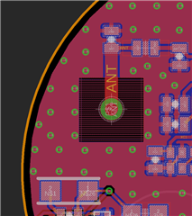
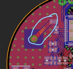
I am designing a custom PCB with the nRF52832, I am going to use wire bent antenna over it. Can I bend feed wire by 45 degree. I have attached image for the part I am talking about.

Please have a look and let me know about it

.

  • Hi,


    Yes, that is fine. While you are at it though you should replicate the reference design a little closer, move the inductor down to align with 'ANT_NRF' and grond the parallel capacitor through pin 31 to the center pad, instead of to the ground pour. You should also add a parallel component (not populated yet) right next to the antenna to allow mounting of a tuning capacitor.


    Best regards,

    Andreas

  • You should model the via and feed.  That thru-hole is massive and between that and the uncharacterized bit of trace running to it you could end up with nothing going to your bent wire.  If you are planning on producing the product like that you will need to come up with a way to fix the position of the wire, like with a plastic frame.  Even small mm changes in its position relative to the board will have huge affects on the RF output.

    Generally people avoid this type of antenna for the reasons above.  You are unlikely to get any consistency in output unless you really nail down the physical characteristics and do a good job matching it. What you are doing really only works well at very low frequencies.

  • I have redesigned and now it is straight and capacitor is grounded as suggested. Please have a look and let me know about it.


  • Hi,


    Replication of the reference layout is better now, but you should still add a keepout in the top layer around C3 and L1 to avoid the risk of your harmonics getting you in trouble.


    As mentioned in another answer, modeling the via and feed would be optimal, but as you might not have the necessary resources on hand it might be better to avoid the number of pitfalls. Regarding the antenna feed, I would remove the square keepout around the feed altogether if you are not able to model it (just having the wire stick right out of the ground plane). As was also mentioned lack of mounting consistency will have an effect on your performance variation, the more variation in your mounting/assembly the more performance will vary between units. Ways to reduce include

    • Antenna soldered with constant/no protrusion through the PCB, preferrably not hand-soldered.
    • Antenna shape similar on all devices (antenna not bent/shaped by hand).
    • Antenna held in place by outer structure, plastic frame etc. in enclosure.

    Non-idealities such as the antenna protruding the PCB will have an impact on performance, but correct tuning should mitigate most of this if done correctly. This particular antenna is relatively wide-band, and therefore quite forgiving in that respect. Regardless, I expect performance to be fair, and should be sufficient unless you have very high requirements.

    I do not know enough about your PCB to know if this is an option or not, but opting for a printed monopole instead yields all the pros of this antenna, but pretty much removes the cons. Of course it requires much more space on the PCB itself. If not an alternative for this board, maybe sometime in the future.


    Best regards,

    Andreas

Related