I'm trying to sample ADC signal using 12 bit ADC resolution, but the digital signal doesn't match the original one seen in the Oscilloscope.
Here are my ADC configurations:
saadc_config.resolution = NRF_SAADC_RESOLUTION_12BIT;

nrf_saadc_channel_config_t channel_0_config =
    NRF_DRV_SAADC_DEFAULT_CHANNEL_CONFIG_SE(NRF_SAADC_INPUT_AIN0);
channel_0_config.gain = NRF_SAADC_GAIN1_6;
channel_0_config.reference = NRF_SAADC_REFERENCE_VDD4;
and sample rate = 250ms.
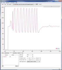
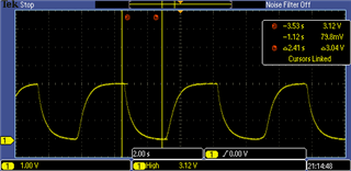
Here is the signal measured in Oscilloscope (20.5 seconds):
And here is the digital signal (same 20.5 seconds):
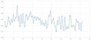
What could be causing these huge differences? I'm expecting to see a sinus-like wave but all I'm seeing is noise.
Can you tell me please what is the optimal configuration for my design? Particularly, gain, reference voltage, etc.
Also, I see that the only options for the reference voltage are 1/4 and 0.6 ("internal"). Isn't there an option to leave it as is? i.e. as it is applied to the BLE on the hardware level?
Please note that the signal is hardware-amplified outside the module, and the input signal as in the first image above is between 0-3V.
Thanks