Beware that this post is related to an SDK in maintenance mode
More Info: Consider nRF Connect SDK for new designs
This post is older than 2 years and might not be relevant anymore
More Info: Consider searching for newer posts

Improving battery life: Use a capacitor ?

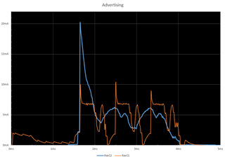
I was wondering if adding a capacitor in parallel with the coin cell battery would help with the battery life by smoothing out the peaks. The scenario shown in the chart is a BLE advertising event (every 1s). I first added a 10uF then also a 100uF capacitor in parallel and took a trace of the power profile. The two series shown is with a 10uF capacitor (orange line) and the other series with both 10uF+100uF capacitors (blue line). Looking at the charts, I have two questions:

1. For the 100uF series, why is there a large spike at the start of the advertising event ? I expected the larger capacitor to help smooth out the initial peak of the advertising event not make it worse. (there's a bit of CPU work before the main spike which is smoothed out but that should not deplete the capacitor). Instead, it looks like its charging at the same time and I suspect there needs to be some way to limit the draw of the capacitor. I tried adding in various resistors but that just converges to not having a capacitor in the first place.

2. It does not look like adding in the 100uF is helping at all, are there ways to make it help and not hurt or is it better to not have it ?
Update:

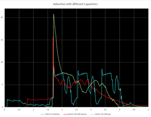
I am using the ppk with an external board thats using an nrf52832. The cap is 100µF ±20% 6.3V Ceramic Capacitor X5R 1210 (Kemet Part #: C1210C107M9PACTU). I re ran the tests using the power select from the ppk (reg) and also using an external supply (cr2450). I noticed some differences between using these two power sources (see chart below). The total charge used between using a cap and not using one seems to be about the same. I have aligned the charts manually so I cant say for sure what the exact alignment is between the scenarios but the added spike is still intriguing but somewhat less when using the battery power source. I had previously read the links provided in the responses below. 
Update 2:

I re ran the tests. For the first results I reported above I used the python version of the ppk UI, and now I tried the new desktop version and got very different results, much more inline with what one would intuitively think about it. So, by adding in the battery as the external supply and the new UI is what gave me intuitive results. I'm going to run it again on a power analyzer to make a final check :-)

  • What kind of a Nordic device are you currently using? Is it a nrf52832? Are you using an SDK example?

    I am unsure why there is a large spike at the start of the advertising event when you use a 100 uF capacitor. Normally, it is a good idea to check out the reference layout that we provide for each of our chips & use the capacitors that are provided in the reference layout (if it is a custom board). 

    It could also be a good idea to take a look at this devzone post. Even though it applies to the nrf51, a lot of it is still similar for the nrf52 device. These two links might also be useful (link 1, link 2).

  • Just thinking out loud, maybe not helpful... At first I thought it could be a sampling artifact: the spike was always there its just that without the larger capacitor, your scope was not sampling frequently enough to catch it.   Then I thought:  but the integral of the first advertisement current (which is power) looks larger in blue than in orange, so the larger capacitor really has changed the power used?  Which is so curious that I think: you must have changed something else, because there is no other explanation?

  • You are correct in assuming reducing ripple caused by the coin cell will improve the battery life.

    Your chart shows the input current to the circuit and not the battery voltage ripple.  It is better to look at the battery voltage ripple but you will see a similar smoothing of the input current spikes.

    The battery voltage ripple is caused by internal losses in the coin cell.  If you look at any CR series battery spec you will see as the load resistance goes down the effective battery capacity goes down.

    Capacitance smooths out the ripple (as it does on any power supply) by providing temporary power storage.

    The problem you are seeing is caused by using the wrong cap.  Caps have internal parasitic inductance and resistance.  If either of these two are high enough the effect of the cap in the circuit is naught for high frequency short duration signals.

    You should be using low esr chip caps and never tantalum or electrolytic. 0805 chip caps can be sourced with low internal inductance (ie, high frequency SRF) at 47uF.  One should easily solve your ripple.

    I would encourage you to take the time to calculate the change in ripple based on the load and a caps exponential model.  You will appreciate the math behind how it works. The theory behind it can be found in any first year engineering textbook.

  • Have a look at this white paper, which dates back to when TI were trying to market their high-consumption BLE parts as coin-cell compatible; it's very useful: Coin cells and peak current draw swra349

  • Thanks, I have updated the question with more details. I am using the ppk to do measurements, and with the ppk power selected to (reg) vs external (cr2450), there is some difference. I have seen the theory but the actual measured data is what I'm trying to use to dictate an approach. 

Related