This post is older than 2 years and might not be relevant anymore
More Info: Consider searching for newer posts

Did not get "Constant carrier wave output for testing" working on nRF24L01+

Hello,

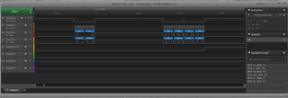
Like in the description, I dont get this to work. Im trying to get The nRF24L01+ connected to a PIC16LF18345. I did Some Pictures of the SPI logic and Here is a Part of the Code Ive written of the configuration for carrier Signal like described in the datasheet.

    while(1)
    {
    if(PORTCbits.RC4 == 0) //Startswitch
    {
    __delay_ms (2500);
        
    spi_start();
    spi_rx(0b00100000); //W + Reg CONFIG
    spi_rx(0x02); //PWR UP
    spi_stop();
    
    __delay_us(1700);
    
    spi_start();
    spi_rx(0b00100110); //W + Reg RF_SETUP
    spi_rx(0b10010110); 
    spi_stop();

    spi_start();
    spi_rx(0b00100101); //W + Reg RF_CH
    spi_rx(0x22); 
    spi_stop();

       while(1){
    PORTCbits.RC7 = 1;  //CE
                }
        }
    }

I have tried almost everything and so now im here and ask for help :) 

  • I have Updated Some Setting because i did a big mistake @ sending data over SPI, but after all, i just dont get this sending a carrier frequency, i have updated the Code in the original post and added a new Picture. Maybe it is the spi but idk what I did wrong.

  • Guys Pls help. I have to create my Technician Work for my State-certified technician for electrical Engineering exam and have this IC choosen for my RF Transaction but atm im desperated and didnt kno how to get this Little step Working for further programming...

  • Here is some Addition Code which my help finding the Problem 

    /// HERE A PAT OF MY INTERRUPT ROUTINE 
    
    void interrupt ISR()
       {
        if (spi_Aktiv == 1)
        
        {
            if (SSP2STATbits.BF == 1)       //BUFFER FULL
            {
                SSP2IF = 0;                 //INTERRUPT FLAG
                spi_BF = 1;                 //BUFFER FULL bit für SPI.H
            }
        }

    /// HERE IS MY SPI FILE (comments in german sry:/)
    
    unsigned char spi_Aktiv = 0;    //Bit für ISR setzen bedeutet: Interrupt betrifft SPI
    unsigned char spi_BF = 0;       //Fuffer Full detection Bit
    void spi_init(){
    
    //PORT B 
        PORTBbits.RB5 = 0;
        PORTBbits.RB7 = 0;
        TRISBbits.TRISB5 = 1;       //Eingang Data In
        TRISBbits.TRISB7 = 0;       //Ausgang Clock
        ANSELBbits.ANSB5 = 0;
        ANSELBbits.ANSB7 = 0;
        LATBbits.LATB5 = 0;
        LATBbits.LATB7 = 0;
        ODCONBbits.ODCB5 = 0;
        ODCONBbits.ODCB7 = 0;
        SLRCONBbits.SLRB5 = 0;
        SLRCONBbits.SLRB7 = 0;
        INLVLBbits.INLVLB5 = 0;
        INLVLBbits.INLVLB7 = 0;
        
     //PORT C   
        PORTCbits.RC1 = 0;
        PORTCbits.RC2 = 0;
        PORTCbits.RC6 = 0;
        PORTCbits.RC7 = 0;
    
        TRISCbits.TRISC1 = 1;       //Eingang Interrupt
        TRISCbits.TRISC2 = 0;       //Ausgang Data OUT
        TRISCbits.TRISC6 = 0;       //Ausgang Slave Select
        TRISCbits.TRISC7 = 0;       //Ausgang R/W
    
        ANSELCbits.ANSC1 = 0;
        ANSELCbits.ANSC2 = 0;
        ANSELCbits.ANSC6 = 0;
        ANSELCbits.ANSC7 = 0;
    
        LATCbits.LATC1 = 0;
        LATCbits.LATC2 = 0;
        LATCbits.LATC6 = 0;
        LATCbits.LATC7 = 0;
    
        ODCONCbits.ODCC1 = 0;
        ODCONCbits.ODCC2 = 0;
        ODCONCbits.ODCC6 = 0;
        ODCONCbits.ODCC7 = 0;
    
        SLRCONCbits.SLRC1 = 0;
        SLRCONCbits.SLRC2 = 0;
        SLRCONCbits.SLRC6 = 0;
        SLRCONCbits.SLRC7 = 0;
    
        INLVLCbits.INLVLC1 = 0;
        INLVLCbits.INLVLC2 = 0;
        INLVLCbits.INLVLC6 = 0;
        INLVLCbits.INLVLC7 = 0;
    
    //PPS
    //-Input
        INTPPS = 0b00010001;  // RC1 Interrupt
        
        //SSP2CLKPPS = 0b00001110; // Clock
        SSP2DATPPS = 0b00001101; //RB5 Data
        //SSP2SSPPS = 0b00001101; //Slave Select
    //-Output
        //RB5PPS = 0b00000000; // -> LATB5 SDI2 MISO
        RB7PPS = 0b00011010; // -> SCK2
        //RC1PPS = 0b00000000; // -> LATC1 INTERRUPT
        RC2PPS = 0b00011011; // -> SDO2 MOSI
        //RC6PPS = 0b00000000; // -> !SS  SlaveSelect
        //RC7PPS = 0b00000000; // -> LATC7 NRF R/W
    //spi
        SSP2ADD = 0b11111111;  //Fosc/(4*(SSPADD[31]+1)) -> 250Kbit
        PORTCbits.RC6 = 1;      //!Slave Select deaktivieren
        SSP2STAT = 0b11000000; // CKE = 1;
        SSP2CON1 = 0b00101010; // SSPEN; CKP = 0; use SSPADD
        SSP2CON3 = 0b00000000; // Bit 4 BOEN vlt falsch
    //Interrupt
        INTCONbits.GIE = 1; //GIE + PEIE = 1
        INTCONbits.PEIE = 1;
        INTCONbits.INTEDG = 1; //Positive Flanke
        PIE0bits.IOCIE = 1; //Periperie Interrupt freischalten
        IOCCP = 0b00000010; //RC1 = interrupt mit Positiver Flanke
        SSP2IE = 1;
    }
    
    
    void spi_start(){
        spi_Aktiv = 1;          //Für interrupt
        PORTCbits.RC6 = 0;      //!Slave Select aktivieren
    }
    
    unsigned char spi_rx(unsigned char txbyte){
    
        SSP2BUF = txbyte;       //Daten in Buffer Schreiben und Übertragung starten
        while(spi_BF == 0){}    //Warten bis Buffer Voll ist (interrupt))
        spi_BF = 0;
        return SSP2BUF;         // Daten aus Buffer Lesen und in spi_rx zurückgeben
                        }
    
    void spi_stop(){
    
        spi_Aktiv = 0;
        PORTCbits.RC6 = 1;      //!Slave Select deaktivieren
        spi_BF = 0;             ////Fuffer Full detection Bit löschen
        
    }

    I have not implemented the Interrupt Routine because there was no Need for the RF carrier Signal in the PDF but if it will help i will add it just tell me.

  • For "I have not implemented the Interrupt Routine because there was no Need for the RF carrier Signal in the PDF but if it will help i will add it just tell me." I mean the Interrupt pin on the nRF, the Code Ive posted is already implemented an working

  • Hi,


    It looks like the device is responding with 0x21 in the first transaction, which is the STATUS register that is shifted out on the MISO pin. This indicates that the TX FIFO is full, and MAX_RT is set.

    In the second transaction, it looks like data is echoed at MISO/MOSI.

    The datasheet states:

    The content of the status register is always read to MISO after a high to low transition on CSN.


    This does not seem to be the case in your logic trace. I would recommend that you check your wired connections.


    Best regards,

    Håkon


Related