This post is older than 2 years and might not be relevant anymore
More Info: Consider searching for newer posts

PWM NEXTSTEP event

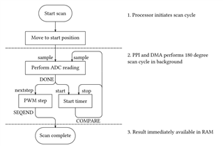
Say I have the PWM Decoder set to NRF_PWM_STEP_TRIGGERED.  If I use NRF_PWM_TASK_NEXTSTEP to step through a PWM sequence, will an event be generated for each step? I would like to step a servo 5 degrees, perform ADC conversion, then repeat for a total of say 180 degrees.

Parents
  • Hello,

    Technically, this would be possible, but if I am not mistaken, the module that uses NRF_PWM_TASKS_NEXTSTEP (I assume you have looked at the example pwm_driver from the SDK?) will run through a sequence with no regards of the ADC. I would consider a more dynamic approach. 


    I would look into a "simpler" way to drive the PWM, using the PPI


    Attached is a simple project using the PPI to control two PWM channels (The LED1 and LED2 on the nRF52832 DK).


    As you see, you can set them up once, and change the PWM signal run time. You can, if you want, use an additional timer (see the timer example from SDK\examples\peripheral\timer) and change the PWM duty cycles on the timeouts if you want that.

    ppi_double_channel_pwm.zip

    At least I find this way of using the PPI to generate PWM signals more comprehensible than the pwm_driver example from the SDK.


    As for you task, this is absolutely possible. You would have to add the ADC part from the saadc example, and trigger the ADC readings when you are in the correct positions.


    Best regards,

    Edvin

  • Hi Edvin,

    Inspired by your proposed solution I've set up the attached flow chart to describe the solution I'm considering. Using a timer does not feel quite as clean as if there had been a dedicated PWM event such as "PWM_EVENT_NEXT_STEP_IN_SEQUENCE_EXECUTED". But oh well :-)

    Edit: On second thought, the timer would probably still be necessary, as it is important that both the servo and IR-sensor has reached steady state before initiating an ADC conversion.

    Flowchart illustrating the scan solution performed mainly via PPI and DMA.

  • Hello,

    The PWM_EVENT_NEXT_STEP_IN_SEQUENCE_EXECUTED will not consider where the motor actually is. It will basically work as a timer, performing a number of periods before moving on to the next sequence. You could also consider waiting for some confirmation from the ADC reading, and use that as a trigger to set the next PWM dutycycle. Maybe it is only me, but I find the PWM examples in the SDK sort of overly complicated. I think they are intended for fancy blinking of LEDs, rather than controlling PWM motors.

    If all you want to do with the PWM is to set a new duty cycle every now and then, and not worry about LED blinking states, then I would prefer using the PPI, but I am not saying that it is the best way for all use cases.

    From my experience with PWM motors, and if I understand your use case correctly, you would start by setting the motor in the reading position, do an ADC reading, and then continue moving the motor to the next position, and so on, it might be easier to use the ADC events as a trigger to go to the next position.


    BR,

    Edvin

Reply
  • Hello,

    The PWM_EVENT_NEXT_STEP_IN_SEQUENCE_EXECUTED will not consider where the motor actually is. It will basically work as a timer, performing a number of periods before moving on to the next sequence. You could also consider waiting for some confirmation from the ADC reading, and use that as a trigger to set the next PWM dutycycle. Maybe it is only me, but I find the PWM examples in the SDK sort of overly complicated. I think they are intended for fancy blinking of LEDs, rather than controlling PWM motors.

    If all you want to do with the PWM is to set a new duty cycle every now and then, and not worry about LED blinking states, then I would prefer using the PPI, but I am not saying that it is the best way for all use cases.

    From my experience with PWM motors, and if I understand your use case correctly, you would start by setting the motor in the reading position, do an ADC reading, and then continue moving the motor to the next position, and so on, it might be easier to use the ADC events as a trigger to go to the next position.


    BR,

    Edvin

Children
  • Hi

    Yes, I agree with you regarding the actual motor position (ref. edit).

    In my proposed design I do use PPI, and it is the ADC that instructs the PWM to proceed to the next duty cycle given in the sequence. Or am I mistaken here? For example, I would set up a PPI channel connected to the ADC "DONE" event in one end, and the PWM's "NEXTSTEP" task in the other end.

  • Hello,

    Yes, you can do that if you use the PWM driver. Just be aware that the project that I linked earlier does not use the PWM driver. It only uses a timer to control a GPIO. But if you use the PWM driver, (the one described here), you can use the PPI to link together the PWM "DONE" with the PWM's "NEXTSTEP".


    Alternatively, if you use the approach in the project that I sent, using the TIMER to control a GPIO, you can wait for the application callback from the ADC to trigger the change in the PWM/TIMER (PPI implementation). It is really up to you. 


    I suspect that we are mixing up a few things here. PPI is typically used for things that are time sensitive, such as generating the PWM signal. The PPI is running in the background, and does not need to interrupt the CPU, or wait for the CPU to run a piece of code. When I first mentioned the PPI, I was thinking of using it to control the GPIO from the timer, to generate the PWM signal, and not to trigger the PWM NEXTSTEP from the ADC event.


    Of course, you can use the PPI for this as well, but I assume that this is not as time sensitive as maintaining the duty cycle of the PWM signal. In other words: it is more important to toggle the GPIO to maintain a PWM duty cycle than to update the duration of the duty cycle. E.g. if you are delayed toggling the GPIO in the PWM signal by 300µs, this will corrupt the PWM signal, telling the motor to go to another position, but if you are delayed updating the length of the duty cycle by 300µs, the motor will stay in the same position for another 300µs, which is not very noticeable.

    Of course, you know your project better than me. If it is very time sensitive to update the duty cycle, then you should use the PPI to do this, but if you want to make sure that the motor has reached the position, stopped and is ready to do a measurement, then I would even considering adding a delay, using a timer, to wait a certain amount of time before starting the ADC sampling. I guess the best way to find out what works is to do some testing with the actual motor.


    Best regards,

    Edvin

Related