This post is older than 2 years and might not be relevant anymore
More Info: Consider searching for newer posts

Counting 250mS Active Low Pulses from a Fault Code LED Indicator

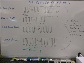
I would like to count fault code pulses that are 250mS active low duration with 250mS between pulses at the end of the pulse train there is a 1.25sec active high.  The pulse train repeat to start a new pulse train.  Pulse codes continue until the fixture is repaired.   We intent to use a nRF52840 in our design.   The application presently flashes an LED on fault alert codes.  It is our intent to decode this fault count with the nRF52840 and advertise the decoded fault via BLE to a Mesh of other peer fixtures.   A gateway will ID the faulty unit for corrective action.

Below is an white board image of active low fault codes with the 1.25sec active high pulse between repeat fault codes.   Looking forward to your assistance as to how to do this with possible timers or capture and compare.   I like to reference example code.    Thank you,  Al Cyr


  • This can be done by counting flanks.

    1. The first negative flank triggers an RTC that will time out after 550ms.
    2. Each negative flank will increment a TIMER in COUNTER mode and reset the RTC.
    3. The RTC will time out when no negative flank has been receive in 550ms.
    4. When the RTC times out, read the value of the COUNTER and clear it, stop the RTC and clear that too. 
  • Is the RTC in item 1 the same timer used in item 2. (ie: is two timers used or one). 

    For item 4; If I read the timer after every 550mS I could read the wrong value unless I continue to read every 500mS and choose the greater count number. 

    Is there a way for a trigger of perhaps another timer that will time out during the 1.25 sec before a new train of pulses.  The 1.25 sec could be used to trigger a counter read.   Your thought on this.    Do you have some sample code on how to set up timers?   

    Thanks, Al

  • "Is the RTC in item 1 the same timer used in item 2. (ie: is two timers used or one). "

    -One RTC and one TIMER.

    "For item 4; If I read the timer after every 550mS I could read the wrong value unless I continue to read every 500mS and choose the greater count number. "

    - Yes you're correct, it should be 550ms the first time and 500ms afterwords.

    "Is there a way for a trigger of perhaps another timer that will time out during the 1.25 sec before a new train of pulses.  The 1.25 sec could be used to trigger a counter read.   Your thought on this. "

    The maximum number of 250ms periods are 9 and 9 * 250ms = 2250ms who is more than the minimum train-to-train duration of 3 * 250 + 1250ms = 2000ms. Therefor you cannot use this method unless the 'resting' duration is increased from 1250 to more than 1500ms or the 250ms periods are decreased to less than 208ms. as given by the equation: 9 * period < 3 * period + resting

    F.ex.

    9 * 250ms < 3 * 250ms + 1600ms or

    9 * 200ms < 3 * 200ms + 1250ms.

    Then we could start an RTC timer at the first flank and count the number of flanks received at 1250ms 


    Do you have some sample code on how to set up timers?  "

    See the RTC, TIMER, PPI and GPIOTE examples, as well as the Peripheral drivers API reference. 

Related