This post is older than 2 years and might not be relevant anymore
More Info: Consider searching for newer posts

Regarding nRF 52832 power consumption SAADC/PPI/TIMER

Hi everybody

I have a couple of questions regarding power consumption for the nRF 52 DK Rev. 1 (nRF52832).

I currently have an application where I sample 12-bit ADC data via the SAADC at a frequency of 8kHz. These samples are stored in buffers of 480 samples. There are two buffers of 480 samples and PPI is enabled (basically the saadc example from the SDK 15). The data is then be compressed via adpcm and sent to a central device via BLE in packages of 240 bytes.

I measured the power consumption with a DC analyzer (as described in the infocenter), I shorted SB12 and cut SB9, applied external power supply at P21 and measured the current at P22.
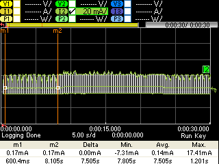
This is the power consumption measurement of my application at 1.8V

There are 3 different consumption levels. Average current as well as min. and max. current can be read out below the images.

1. Not connected to central device and advertising (SAADC/PPI/TIMER not running)

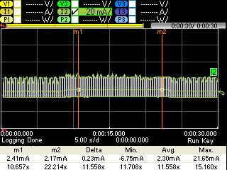
2.  Connected to central device and sampling as well as streaming data. (SAADC/PPI/TIMER enabled via NOTIFICATION_ENABLED request from central)

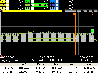
3. Disconnected and advertising again  (SAADC/PPI/TIMER stopped)

Question 1:

I was unable to find the reason for the difference in current consumption between phase 1 and 3 (0.14mA to 0.8mA). What could be the reason for the difference in current of 0.66mA?

As mentioned previously, I initialize SAADC/PPI/TIMER upon a NOTIFICATION_ENABLED request from central. This is done in the same way as in the saadc example from SDK 15.

static void initalize_saadc(void)
{
    saadc_init();
    saadc_sampling_event_init();
    saadc_sampling_event_enable();
}

void saadc_sampling_event_init(void)
{
    ret_code_t err_code;

    err_code = nrf_drv_ppi_init();
    APP_ERROR_CHECK(err_code);

    nrf_drv_timer_config_t timer_cfg = NRF_DRV_TIMER_DEFAULT_CONFIG;
    timer_cfg.bit_width = NRF_TIMER_BIT_WIDTH_32;
    err_code = nrf_drv_timer_init(&m_timer, &timer_cfg, timer_handler);
    APP_ERROR_CHECK(err_code);

    /* setup m_timer for compare event every 400ms */
//    uint32_t ticks = nrf_drv_timer_ms_to_ticks(&m_timer, 100);
    uint32_t ticks = nrf_drv_timer_us_to_ticks(&m_timer, 125);
    nrf_drv_timer_extended_compare(&m_timer,
                                   NRF_TIMER_CC_CHANNEL0,
                                   ticks,
                                   NRF_TIMER_SHORT_COMPARE0_CLEAR_MASK,
                                   false);
    nrf_drv_timer_enable(&m_timer);

    uint32_t timer_compare_event_addr = nrf_drv_timer_compare_event_address_get(&m_timer,
                                                                                NRF_TIMER_CC_CHANNEL0);
    uint32_t saadc_sample_task_addr   = nrf_drv_saadc_sample_task_get();

    /* setup ppi channel so that timer compare event is triggering sample task in SAADC */
    err_code = nrf_drv_ppi_channel_alloc(&m_ppi_channel);
    APP_ERROR_CHECK(err_code);

    err_code = nrf_drv_ppi_channel_assign(m_ppi_channel,
                                          timer_compare_event_addr,
                                          saadc_sample_task_addr);
    APP_ERROR_CHECK(err_code);
    
}

The peripherals are then stopped upon a BLE_GAP_EVT_DISCONNECTED event in the following way:

static void uinitalize_saadc(void)
{
    nrf_drv_timer_disable(&m_timer);
    nrf_drv_timer_uninit(&m_timer);
    
    nrf_drv_ppi_channel_disable(m_ppi_channel);
    nrf_drv_ppi_uninit();

    nrf_drv_saadc_abort();
    nrf_drv_saadc_uninit();
}

The closeup of phase 1 looks as follows (section without advertising peaks):

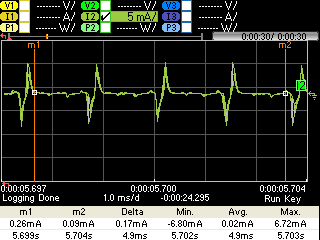
Here the closeup of phase 3 can be seen:

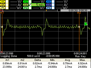
It looks as though there is still some peripheral running. However, I cannot figure out which one.

Question 2:

Is the power consumption of phase 1 and 2 reasonable? 

Phase 1: Advertising interval 300 (0.625 ms units)

Phase 2: min. connection interval 15 (1.25 ms units), max. connection interval 30 (1.25 ms units), package size 240 bytes, slave latency 0, data stream after audio compression ca. 15kbit/s

Question 3:

How could the power consumption be further improved? From what I read most current stems from PPI which uses Easy DMA. Is there a way around this in my case (single channel, 8kHz sampling frequency)?

Turned out to be quite a long post, would be really glad if someone could help me.

Best,

Nick

Parents
  • Hey Nick7,

    1. Can you enter a debug session and read the registers of the peripherals you're using, when you should normally be at sleep? For Phase 1 and Phase 3.

    2. Phase 1: Advertising interval of ~200ms should use ~70µA at 0dBm TX output. What is your TX output?
      Phase 2: It depends on how much CPU time the compression uses. 
    3. We need more information on what exactly your current consumption issues are before we can point to anything specific. 

    I'd like to measure the current on a nRF52DK, do you mind sharing a hex file i can test?

    Cheers,

    Håkon.

  • Hey Håkon

    Thanks for the reply.

    1. I don't think it's possible to set breakpoints while Softdevice is running. So I read out the register values using log:

    For SAADC I read out the ENABLE register value (at 0x40007500). This bit starts at 0 in phase 1 and returns to 0 in phase 3.

    For PPI I read out the CHEN values (at 0x4001f500). CH31 is enabled the whole time, I think it's used for the softdevice. CH0 starts out at 0 in phase 1 and returns to 0 in phase 3.

    Regarding the TIMER, I did not know which register value to check. I could not find any changes in the CC[0], INTENSET, INTENCLEAR or MODE registers (all values 0 in all phases). However, when checking the BITMODE register it got a change in the register from 00 to 11 upon entering phase 2. This change was present for phase 3 as well. Which leads me to believe that maybe the timer was not correctly uninitialized. I observed similar behavior for the EVENTS_COMPARE[0] register (phase 1 = 0, phase 2 and 3 != 0).

    2. How should I read out the TX power? via the nRF connect app I get values between -50dBm and -70dBm.

    I attached the hex. files. Thanks for taking a look.

    3240.ble_app_template_pca10040_s132.hex

    ble_app_uart_c_pca10040_s132.hex

    The peripheral one is ble_app_template (this is the one with the power consumption issue). The other application is the central.

    Best,

    Nick

    1. You can use breakpoints or stop the CPU at any time and read the registers, but you cannot continue execution as the SoftDevice will crash. Our supported IDEs have special view windows to read the content of our peripherals registers. They are very useful when debugging. F.Ex. In Segger Embedded studio, enter debug mode click View->Registers->Registers 1->Groups.
    2. Tx power is set as an option when intializing the advertisments. See sd_ble_gap_tx_power_set API docs. 
      Be careful when using RSSI, it measures only the energy in the receiver when a packet is received, not link quality or the distance from transmitter, etc.
Reply
    1. You can use breakpoints or stop the CPU at any time and read the registers, but you cannot continue execution as the SoftDevice will crash. Our supported IDEs have special view windows to read the content of our peripherals registers. They are very useful when debugging. F.Ex. In Segger Embedded studio, enter debug mode click View->Registers->Registers 1->Groups.
    2. Tx power is set as an option when intializing the advertisments. See sd_ble_gap_tx_power_set API docs. 
      Be careful when using RSSI, it measures only the energy in the receiver when a packet is received, not link quality or the distance from transmitter, etc.
Children
No Data
Related