
Hi all,
I am newbie with nordic, and I need some help.
I am using nRF52832 with softdevice.
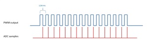
I need to generate a 128 kHz clock signal (PWM pulses with 128kHz frequency, duty cycle 50%,) and to sample Analog input at the same frequency (128 kHz) which is synced to the generated pulses (one sample to each cycle of the PWM output)
after some research and reading PWM ,PPI and SAADC documentation. I wrote this attached code
I managed to generate the PWM but I can't connect it to the through PPI to start ADC sampling.
please give me some advises or suggestion to correct it.
Regards,
void pwm_init(void)
{
uint32_t out_pins[] = {18, NRF_PWM_PIN_NOT_CONNECTED, NRF_PWM_PIN_NOT_CONNECTED, NRF_PWM_PIN_NOT_CONNECTED};
static uint16_t pwm_seq[2] = {62, 62};
nrf_pwm_sequence_t const seq =
{
.values.p_common = pwm_seq,
.length = sizeof(pwm_seq)/sizeof(uint16_t),
.repeats = 0,
.end_delay = 0
};
//nrf_gpio_cfg_output(5);
nrf_pwm_pins_set(NRF_PWM0, out_pins);
nrf_pwm_enable(NRF_PWM0);
nrf_pwm_configure(NRF_PWM0, NRF_PWM_CLK_16MHz, NRF_PWM_MODE_UP, 124);
nrf_pwm_loop_set(NRF_PWM0, 0);
nrf_pwm_decoder_set(NRF_PWM0, NRF_PWM_LOAD_COMMON, NRF_PWM_STEP_AUTO);
nrf_pwm_sequence_set(NRF_PWM0, 0, &seq);
NRF_PWM0->TASKS_SEQSTART[0] = 1;
}
void saadc_init(void)
{
ret_code_t err_code;
nrf_saadc_channel_config_t channel_config =
NRF_DRV_SAADC_DEFAULT_CHANNEL_CONFIG_SE(3);
err_code = nrf_drv_saadc_init(NULL, saadc_callback);
APP_ERROR_CHECK(err_code);
err_code = nrf_drv_saadc_channel_init(0, &channel_config);
APP_ERROR_CHECK(err_code);
err_code = nrf_drv_saadc_buffer_convert(m_buffer_pool[0], SAMPLES_IN_BUFFER);
APP_ERROR_CHECK(err_code);
/*err_code = nrf_drv_saadc_buffer_convert(m_buffer_pool[1], SAMPLES_IN_BUFFER);
APP_ERROR_CHECK(err_code);*/
}
void saadc_sampling_event_init(void)
{
ret_code_t err_code;
err_code = nrf_drv_ppi_init();
APP_ERROR_CHECK(err_code);
uint32_t pwm_pulse_event_addr = nrf_pwm_task_address_get(NRF_PWM0, NRF_PWM_EVENT_STOPPED );
uint32_t saadc_sample_task_addr = nrf_drv_saadc_sample_task_get();
#if 1
/* setup ppi channel so that timer compare event is triggering sample task in SAADC */
err_code = nrf_drv_ppi_channel_alloc(&m_ppi_channel);
APP_ERROR_CHECK(err_code);
err_code = nrf_drv_ppi_channel_assign(m_ppi_channel,
pwm_pulse_event_addr,
saadc_sample_task_addr);
APP_ERROR_CHECK(err_code);
#endif
}
void saadc_sampling_event_enable(void)
{
ret_code_t err_code = nrf_drv_ppi_channel_enable(m_ppi_channel);
APP_ERROR_CHECK(err_code);
}
void saadc_callback(nrf_drv_saadc_evt_t const * p_event)
{
if (p_event->type == NRF_DRV_SAADC_EVT_DONE)
{
ret_code_t err_code;
err_code = nrf_drv_saadc_buffer_convert(p_event->data.done.p_buffer, SAMPLES_IN_BUFFER);
APP_ERROR_CHECK(err_code);
int i;
printf("ADC event number: %d\r\n", (int)m_adc_evt_counter);
for (i = 0; i < SAMPLES_IN_BUFFER; i++)
{
printf("%d ", p_event->data.done.p_buffer[i]);
}
printf("\n\r");
}
}
void main()
{
pwm_init();
saadc_init();
saadc_sampling_event_init();
saadc_sampling_event_enable();
}
