This post is older than 2 years and might not be relevant anymore
More Info: Consider searching for newer posts

Interrupts on many pins high to low

I want to detect high to low transitions on 28 GPIO independently. I've read in other posts you can configure 4 pin interrupts or a port interrupt for all pins, but I'm not sure that allows the pins to have different states and still be detected.

I'm using GPIOTE. The code below does not seem to work for all pins.

for(int i = 2; ...; i++) {
    nrf_drv_gpiote_in_config_t in_config = GPIOTE_CONFIG_IN_SENSE_TOGGLE(false);
    in_config.pull = NRF_GPIO_PIN_NOPULL;
    err_code = nrf_drv_gpiote_in_init(i, &in_config, in_pin_handler);
    VERIFY_SUCCESS(err_code);
    nrf_drv_gpiote_in_event_enable(i, true);
}

Is the only solution polling?

Parents Reply Children
  • Yes I do eventually check the error code (I originally received NRFX_ERROR_NO_MEM as NRFX_GPIOTE_CONFIG_NUM_OF_LOW_POWER_EVENTS was set to default 4, I increased to 28), it always succeeds

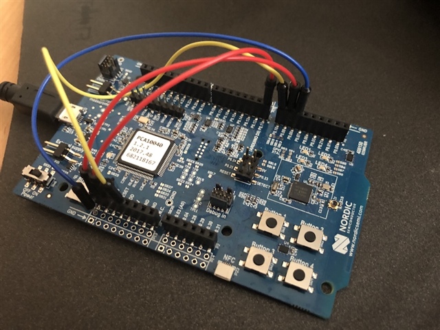
  • To reproduce, copy the following code into the blinky example, replacing main(). Connect P0.8 to P0.11 to VDD as shown. Only pins 8 and 11 interrupt for me.

    #include "nrf_drv_gpiote.h"
    #include "nrf_gpiote.h"
    
    void in_pin_handler(nrf_drv_gpiote_pin_t pin, nrf_gpiote_polarity_t action) {
        NRF_LOG_INFO("Pin %d action %d", pin, action);
    }
    
    
    /**@brief Function for application main entry.
     */
    int main(void)
    {
        // Initialize.
        log_init();
        //leds_init();
        //timers_init();
        //buttons_init();
        power_management_init();
        //ble_stack_init();
        //gap_params_init();
        //gatt_init();
        //services_init();
        //advertising_init();
        //conn_params_init();
    
    
        ret_code_t err_code = NRF_SUCCESS;
        if(!nrf_drv_gpiote_is_init()) {
            err_code = nrf_drv_gpiote_init();
            APP_ERROR_CHECK(err_code);
        }
    
        for(int i = 8; i < 12; i++) {
            nrf_drv_gpiote_in_config_t in_config = GPIOTE_CONFIG_IN_SENSE_TOGGLE(false);
            in_config.pull = NRF_GPIO_PIN_PULLDOWN;
            err_code = nrf_drv_gpiote_in_init(i, &in_config, in_pin_handler);
            APP_ERROR_CHECK(err_code);
            nrf_drv_gpiote_in_event_enable(i, true);
        }
    
        // Start execution.
        NRF_LOG_INFO("Blinky example started.");
        //advertising_start();
    
        // Enter main loop.
        for (;;)
        {
            idle_state_handle();
        }
    }

  • P0.09 and P0.10 are the NFCT antenna pins. Did you define the symbol CONFIG_NFCT_PINS_AS_GPIOS in your project, and solder 0-ohm resistors from R25/R26 to R27/R28, to connect the GPIOs to the pin headers?

  • No, are there 28 pins where I don’t need to make changes and can just be used as GPIO as they are? We may want to use NFC on this project in the future anyway.

  • There are 32 GPIOs on the nRF52832. Some of these GPIOs have shared pins with other features, as described in the pin mappings documentation. On the DK, at least P0.00, P0.01 (XL1, XL2 - low frequency crystal), P0.09, P0.10 (NFCT antenna pins), and P0.21 (nRESET) are not connected to the pin headers on the nRF52-DK. The rest of the pins should all be connected to the headers, but note that many of them are connected to things (P0.05-P0.08 used for UART, P0.13-P0.20 connected to LEDs and buttons, etc.). To use 28 GPIOs on the DK, you need to repurpose and connect at least one of these pins. If you need more GPIOs you need to upgrade to nRF52840, which have up to 48 GPIOs.

Related