This post is older than 2 years and might not be relevant anymore
More Info: Consider searching for newer posts

NRF52832 Antenna Design

Hello,

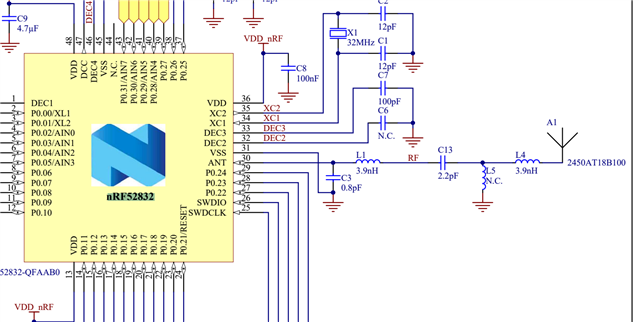
I am trying to evaluate the NRF52832 on a custom board and i will design the antenna according to your NRF52 Thingy:52 design. I am quite a newbie about RF&Antennas so I got some questions. In this specific design, the L1 and C3 are the 50ohm matching network. But what about C13/L4 (and maybe L5? it is not connected, so i am not sure if i should use it). It should be a T-network or a PI-network but doesn't look like it.

Can you please explain to me, how does this work?

I didn;'t find a clear answer on other topics.

Thanks a lot!

In 

  • There is no simple answer on any of this.  All antennas require matching to operate on the intended board.  Only if you literally copy precisely a design can you expect to reuse a reference design match. So, if you change absolutely anything at all you can assume you will have to rematch your antenna.

    Matching requires a VNA and someone who knows how to use it.

    In the schematic above, L1 and C3 match the nRF to 50 ohms. They are predictable as long as you follow the reference layout artwork. Anything on the antenna side will be different for your board.  Most .062" 2 layer boards do not have 50ohm traces simply because they are too wide to work with. This makes your work more difficult as changing the electrical length of the nRF to antenna connection affects the match considerably.

    In the schematic above, the Johanson is spec'd to have a 9.5dB return loss without a match assuming you follow their ground plane guidelines. A 2.2pF and 3.9nH very nearly form a series bandpass filter at 2.4GHz and with the electrical length from the pads for L5 probably does so reasonably well.  Likely these values were chosen not for matching but rather for harmonic suppression.

Related