This post is older than 2 years and might not be relevant anymore
More Info: Consider searching for newer posts

Antenna load impedance simulation result is far from 15Ω+j88Ω.

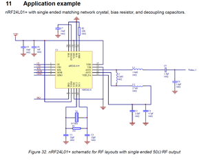
Based on the Product Specification v1.0, the antenna load impedance should be 15Ω+j88Ω. 

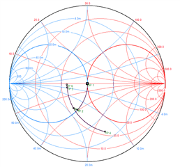
I checked the antenna impedance based on Figure 32. 

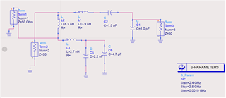
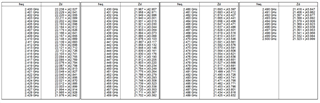
The simulation result is 

For the differential impedance Zd, I used the following equation

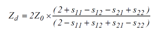
The simulated result is about 21Ω+j43Ω, far from 15Ω+j88Ω. 

Anyone can help to check this problem. 

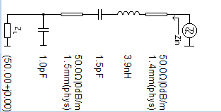
I want to fine tune the external circuit based on the S11 of my own PCB antenna. 

thanks in advance. 

-Tony

Parents
  • You need to have a much more advanced simulation model if you want to do this accurate enough. The PCB and layout (tracks and pads) are major part of the design. Also the components will behave different at 2.4 GHz than at lower frequencies. You need to use a model for the components, not ideal components. 

    In any case, you need to go via a 50 ohm point if you want to do any conducted measurements. If you adapt the output of the matching network to match the antenna impedance, you have no place to connect to for conducted measurements and all measurements and fine tuning must be done in an anechoic chamber

  • Hi Ketiljo, 

    Thank you for your help. I can add real component (Murata caps and inductors) model and the track and pads into the simulation. 

    I made a rough estimation 

    The effect of 1.5mm transmission line does not change the point on the Smith chart too much. 

    In nordic, do you have a simulation model for this circuit? 

    -Tony

  • The estimation still uses ideal components. You need to simulate the complete design included track inductance and capacitance to ground. 

    We have a simulation model but this contains the RF front end as well so we can't publish this.

  • The result is similar to ideal component model,  still far from 15Ω+j88Ω. Please help to check. 

  • It's not easy to include all effects of the layout and components. The value 15 +j88 ohm is measured on the differential side of the matching network, chip removed and antenna port terminated with 50 ohm

    Not sure what you have to gain on this. It's more to the matching network than just impedance transformation. It also does harmonic filtering and RX LO suppression. This is not possible to simulate so you must measure this in any case. You will need to have a 60 ohm point to do measurements so all the components in the matching network are needed. 

Reply
  • It's not easy to include all effects of the layout and components. The value 15 +j88 ohm is measured on the differential side of the matching network, chip removed and antenna port terminated with 50 ohm

    Not sure what you have to gain on this. It's more to the matching network than just impedance transformation. It also does harmonic filtering and RX LO suppression. This is not possible to simulate so you must measure this in any case. You will need to have a 60 ohm point to do measurements so all the components in the matching network are needed. 

Children
Related