This post is older than 2 years and might not be relevant anymore
More Info: Consider searching for newer posts

Antenna load impedance simulation result is far from 15Ω+j88Ω.

Based on the Product Specification v1.0, the antenna load impedance should be 15Ω+j88Ω. 

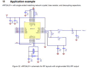
I checked the antenna impedance based on Figure 32. 
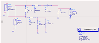
The simulation result is 

For the differential impedance Zd, I used the following equation

The simulated result is about 21Ω+j43Ω, far from 15Ω+j88Ω. 

Anyone can help to check this problem. 

I want to fine tune the external circuit based on the S11 of my own PCB antenna. 

thanks in advance. 

-Tony

  • It's not easy to include all effects of the layout and components. The value 15 +j88 ohm is measured on the differential side of the matching network, chip removed and antenna port terminated with 50 ohm

    Not sure what you have to gain on this. It's more to the matching network than just impedance transformation. It also does harmonic filtering and RX LO suppression. This is not possible to simulate so you must measure this in any case. You will need to have a 60 ohm point to do measurements so all the components in the matching network are needed. 

  • @ketiljo, it's simulation. term3 is perfect 50 ohm. term1 and term2 are used to measure and calculate the differential impedance. 

    I insist to simulate this circuit is to make sure the circuit provided in the spec is CORRECT. 

    But based on my current simulation, it maybe WRONG. 

    I am really happy if there is anyone can help to correct me. 

Related