This post is older than 2 years and might not be relevant anymore
More Info: Consider searching for newer posts

NRF52832 using GPIOTE and PPI to measure both low's and high's of a pulse with SD enabled.

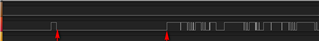
Hi all, we're using code from this forum to enable GPIOTE and PPI to measure the low between the arrows to indicate a "start of transmission" and then switch to measuring the highs after that. But so far, I can only measure one or the other (high or low) without re configuring the GPIOTE. Any ideas?

static void gpiote_init(uint32_t pin)
{

  //Set up 2 events on the input pin, one for a HiToLo event and one for a LoToHi event
  NRF_GPIOTE->CONFIG[0] = ((GPIOTE_CONFIG_MODE_Event      << GPIOTE_CONFIG_MODE_Pos)
                         | (pin                           << GPIOTE_CONFIG_PSEL_Pos)
                         | (GPIOTE_CONFIG_POLARITY_LoToHi << GPIOTE_CONFIG_POLARITY_Pos)
                         | (GPIOTE_CONFIG_OUTINIT_Low     << GPIOTE_CONFIG_OUTINIT_Pos));

  NRF_GPIOTE->CONFIG[1] = ((GPIOTE_CONFIG_MODE_Event      << GPIOTE_CONFIG_MODE_Pos)
                         | (pin                           << GPIOTE_CONFIG_PSEL_Pos)
                         | (GPIOTE_CONFIG_POLARITY_HiToLo << GPIOTE_CONFIG_POLARITY_Pos)
                         | (GPIOTE_CONFIG_OUTINIT_Low     << GPIOTE_CONFIG_OUTINIT_Pos));


  //The PPI provides a mechanism to automatically trigger a task in one peripheral as a result of an event
  //occurring in another peripheral. 
  NRF_PPI->CH[0].EEP = (uint32_t)&NRF_GPIOTE->EVENTS_IN[0];     //Event End Point: TIES PIN1 Event TO PPI0
  NRF_PPI->CH[0].TEP = (uint32_t)&NRF_TIMER1->TASKS_START;      //Task End Point: TIES PIN 1 TO START Task
	
  NRF_PPI->CH[1].EEP = (uint32_t)&NRF_GPIOTE->EVENTS_IN[1];     //TIES PIN2 Event TO PPI1
  NRF_PPI->CH[1].TEP = (uint32_t)&NRF_TIMER1->TASKS_CAPTURE[0]; //CAPTURE TIMER TO CC[0]
  //Each TEP implements a fork mechanism that enables a second task to be triggered at the same time as
  //the task specified in the TEP is triggered.
  NRF_PPI->FORK[1].TEP = (uint32_t)&NRF_TIMER1->TASKS_STOP;     //Second task: STOP TIMER when event fires
		
  NRF_PPI->CHENSET     = (PPI_CHEN_CH0_Msk | PPI_CHEN_CH1_Msk); //Turns on PPI0,1
				
  NVIC_EnableIRQ(GPIOTE_IRQn);
				
  // Enable interrupt on input 1 event.
 NRF_GPIOTE->INTENSET = GPIOTE_INTENSET_IN1_Msk;

}

Parents
  • Hello,

    You must re-configure the PPI channels in order to switch from reading the lows and reading the highs.

    Alternatively, you can try to not stop the TIMER on NRF_PPI->FORK[1].TEP, but instead use another CC register to capture the time between LOTOHI and HITOLO. Then you must read out the CC value, and compare it to the last time, in order to calculate the difference, but it should be possible.


    In pseudo code:

    NRF_TIMER1->TASKS_START = 1; // call this from the application layer)
    
    PPI->CH[0].EEP = GPIOTE->EVENTS_IN[0];
    PPI->CH[0].TEP = TIMER->TASKS_CAPTURE[0];
    
    PPI->CH[1].EEP = GPIOTE->EVENTS_IN[1];
    PPI->CH[0].TEP = TIMER->TASKS_CAPTURE[1];
    
    NRF_PPI->CHENSET (CH0_Msk | CH1_Msk);
    
    NVIC_EnableIRQ(GPIOTE_IRQn);


    Then read the CC registers in the application and compare it to the previous interrupt to figure out how many ticks that has passed since last interrupt. This way you can get the interrupts from both HITOLO and LOTOHI, and you decide which interrupts you want to deal with in the application.


    Best regards,

    Edvin

Reply
  • Hello,

    You must re-configure the PPI channels in order to switch from reading the lows and reading the highs.

    Alternatively, you can try to not stop the TIMER on NRF_PPI->FORK[1].TEP, but instead use another CC register to capture the time between LOTOHI and HITOLO. Then you must read out the CC value, and compare it to the last time, in order to calculate the difference, but it should be possible.


    In pseudo code:

    NRF_TIMER1->TASKS_START = 1; // call this from the application layer)
    
    PPI->CH[0].EEP = GPIOTE->EVENTS_IN[0];
    PPI->CH[0].TEP = TIMER->TASKS_CAPTURE[0];
    
    PPI->CH[1].EEP = GPIOTE->EVENTS_IN[1];
    PPI->CH[0].TEP = TIMER->TASKS_CAPTURE[1];
    
    NRF_PPI->CHENSET (CH0_Msk | CH1_Msk);
    
    NVIC_EnableIRQ(GPIOTE_IRQn);


    Then read the CC registers in the application and compare it to the previous interrupt to figure out how many ticks that has passed since last interrupt. This way you can get the interrupts from both HITOLO and LOTOHI, and you decide which interrupts you want to deal with in the application.


    Best regards,

    Edvin

Children
Related