This post is older than 2 years and might not be relevant anymore
More Info: Consider searching for newer posts

TWI with SDK v14.2.0 and IQS231A

Dear Nordic Team,

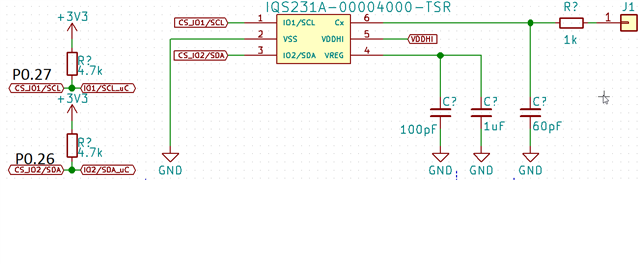
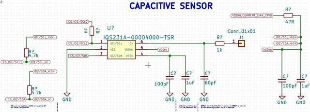
We are using nRF52832 with a IQS231A for proximity detection for a new product, the pins are connected to SDA and SCL and everything is routed as in datasheet. however, I got to know today this sensor can only enter I2C mode in "test mode" which last for 340ms at initialization, and during this time we can access the I2C, this is done for power consumption purposes.

however, this requires polling the device at the start within 340ms and recieving the ACK this also includes burning the setting to the IC within this time window, my question. is the nRF52832 able to communicate at this speed ?, i tried the TWI scanner example but no device was found, changed to frequency to higher speed  400KB but still no device was found on I2C bus. Are you aware of any possible solution ? is it possible if there is any code sample that we can test as a biginning. an idea would be to supply the VDD directly from the the nordic chip, but what is maximum current that can the pins can supply without disrupting.

datasheet for the sensor can be found here:

https://www.mouser.com/ds/2/42/iqs231a_datasheet-1062577.pdf

The way to access the test mode/I2C mode can be found here:

https://www.mouser.com/pdfdocs/AZd0981QS231OTPconfiguration-2.pdf

I look forward for your reply,

Moe

  • Here is a schematic for the current cap sense, with a pullup resistors of 4.7K:

    - SCL is routed to pin P0.27.

    -SDA is routed to pin P0.26.


    Note: I also also removed the pull-up resistors but it didnt work.

  • Hi Moe,

    To find the working 7-bit devices address you can run the TWI scanner example, however if the TWI only is operational for 340ms after power on, you likely will need to power the sensor from a GPIO on the nRF52832, and the toggle this GPIO low between each attempt to interface with the sensor. This will ensure you can discover the correct address to interface the sensor. Once you know the address it should be no problem to write and read any data you like well within the 340ms.

    Best regards,
    Kenneth

  • Hi Kenneth,


    Thanks for your answer, so in the last days i tried to work around a code to make the device entering in test mode so i can initialize the sensor, i tried to build upon the example provided "TWI sensor example, here is my code:


    #include <stdio.h>
    #include "boards.h"
    #include "app_util_platform.h"
    #include "app_error.h"
    #include "nrf_drv_twi.h"
    #include "nrf_delay.h"
    
    
    #include "nrf_log.h"
    #include "nrf_log_ctrl.h"
    #include "nrf_log_default_backends.h"
    
    /*************************************************************************/
    #include "nrf_drv_gpiote.h"
    #include "nrf_delay.h"
    
    /* TWI instance ID. */
    #define TWI_INSTANCE_ID     0
    
    /******************************IQS231A at test mode**********************************************/
    #define IQS231A_I2C_ADDR_TEST_MODE        (0x45U >> 1) //entering test mode aka I2C mode
    																										
    /********************************OTP test mode RAM addresses*******************************************************/
    #define OTP_BANK_0					0x10U  //check setting...it doesnt exist ?
    #define OTP__BANK_1 				0x11U 
    #define OTP_BANK_2					0x12U
    #define OTP_BANK_3					0x13U
    /*********************************Memory map I2C reg*********************************************/
    
    #define PRODUCT_NUMBER 			0x00U
    #define SOFTWARE_VERSION		0x01U
    #define	DEBUG_EVENTS			0x02U
    #define COMMANDS				0x04U
    
    #define QUICK_RELEASE			0x08U
    #define MOVEMENT				0x09U
    #define PROX_THRESHOLDS			0x0BU
    #define	CH_0_MULTIPLIERS		0x0DU
    #define	CH_1_MULTIPLIERS		0x0FU
    #define SYSTEM_FLAGS			0x11U
    #define UI_FLAGS				0x12U
    #define EVENT_FLAGS				0x14U
    #define CH0_ACF_H				0x15U
    #define CH0_ACF_L				0x16U
    #define CH0_LTA_H				0x17U
    #define CH0_LTA_L				0x18U
    #define CH0_QRD_H				0x19U
    #define	CH0_QRD_L				0x1AU
    #define	CH1_ACF_H				0x1BU
    #define	CH1_ACF_L				0x1CU
    #define	CH1_UMOV_H				0x1DU
    #define	CH1_UMOV_L				0x1EU
    #define	CH1_LMOV_H				0x1FU
    #define	CH1_LMOV_L				0x20U
    #define REGISTER_ADDRESS_CONFIRM_TEST_MODE 0x0FU
    
    #define VDDHI_PIN			    22
    
    /***************TIMINGS*********************/
    #define T_init					2


    /* Indicates if operation on TWI has ended. */
    static volatile bool m_xfer_done = false;
    
    /* TWI instance. */
    static const nrf_drv_twi_t m_twi = NRF_DRV_TWI_INSTANCE(TWI_INSTANCE_ID);
    
    /* Buffer for samples read from temperature sensor. */
    static uint8_t m_sample;
    
    /**
     * @brief Function for switching on VDDHI
     */
    
    void init_vddhi_on(nrf_drv_gpiote_pin_t pin, nrf_gpiote_polarity_t action)
    {
    
    	ret_code_t err_code;
    	    if(!nrf_drv_gpiote_is_init()) {
            nrf_drv_gpiote_init();
    			}
    			
    			/****configure P0.22 VDDHI as output********/
    			nrf_drv_gpiote_out_config_t vddhi_config = GPIOTE_CONFIG_OUT_SIMPLE(0);
    			err_code = nrf_drv_gpiote_out_init(VDDHI_PIN, vddhi_config);
    			//nrf_gpio_pin_set(VDDHI_PIN);
    			APP_ERROR_CHECK(err_code);
    }
    
    /**
     * @brief Function for writing the setting for IQS231A capacitive sensor
     */
    
    void IQS231A_switch_to_test_mode(void)
    {
    
    	ret_code_t err_code;
    	uint32_t level;
    	uint32_t reg[0] = REGISTER_ADDRESS_CONFIRM_TEST_MODE; //0x0F
    	
    	nrf_gpio_pin_set(VDDHI_PIN);
    	level = nrf_gpio_pin_read(VDDHI_PIN);
    	
    	/*check if device pulled high then initialize the sensor*/
    	if(level == true){
    		
    		
    		nrf_delay_ms(T_init); // wait for the cap sensor initialization time
    		/**/
        err_code = nrf_drv_twi_tx(&m_twi, IQS231A_I2C_ADDR_TEST_MODE, reg, sizeof(reg), false);
    		APP_ERROR_CHECK(err_code);
    		
    	}


    however, according to the datasheet here, Page2, section 3 ("Entering Test mode"), i need to read the data and check if data = A5, how can I do this ?

    also the ACK should be recieved, how can i check if ACK is recieved ?


    Thanks a lot in advance,

    Mohamed

    Edit: right now VDDHI is connected to  a GPIO

    I am using Nordic devkit and VDDHI is connected to pin P0.22


  • Hi Kenneth,


    So I followed exactly the example in the thread that you mentioned here, but unfortunately i was not able to have an I2C/ TWI signal in my logic analyzer, I was able to have some sort of a signal, My new code goes like this:

    #include <stdio.h>
    #include "boards.h"
    #include "app_util_platform.h"
    #include "app_error.h"
    #include "nrf_drv_twi.h"
    #include "nrf_delay.h"
    #include "nrf_log.h"
    #include "nrf_log_ctrl.h"
    #include "nrf_log_default_backends.h"
    #include "nrf_drv_gpiote.h"
    #include "nrf_delay.h"
    
    /**********************new includes****************************************/
    
    /* TWI instance ID. */
    #define TWI_INSTANCE_ID     0
    
    
    /******************************IQS231A at test mode**********************************************/
    #define IQS231A_I2C_ADDR_TEST_MODE        (0x45U >> 1) //entering test mode aka I2C mode
    
    #define REGISTER_ADDR_CONFIRM_TEST_MODE 0x0F
    																										
    /********************************OTP test mode RAM addresses*******************************************************/
    #define OTP_BANK_0			0x10U  
    #define OTP__BANK_1 			0x11U 
    #define OTP_BANK_2			0x12U
    #define OTP_BANK_3			0x13U
    /*********************************Memory map I2C reg*********************************************/
    
    #define PRODUCT_NUMBER 			0x00U
    #define SOFTWARE_VERSION		0x01U
    #define	DEBUG_EVENTS			0x02U
    #define COMMANDS			0x04U
    #define QUICK_RELEASE			0x08U
    #define MOVEMENT			0x09U
    #define PROX_THRESHOLDS			0x0BU
    #define	CH_0_MULTIPLIERS		0x0DU
    #define	CH_1_MULTIPLIERS		0x0FU
    #define SYSTEM_FLAGS			0x11U
    #define UI_FLAGS			0x12U
    #define EVENT_FLAGS			0x14U
    #define CH0_ACF_H			0x15U
    #define CH0_ACF_L			0x16U
    #define CH0_LTA_H			0x17U
    #define CH0_LTA_L			0x18U
    #define CH0_QRD_H			0x19U
    #define	CH0_QRD_L			0x1AU
    #define	CH1_ACF_H			0x1BU
    #define	CH1_ACF_L			0x1CU
    #define	CH1_UMOV_H			0x1DU
    #define	CH1_UMOV_L			0x1EU
    #define	CH1_LMOV_H			0x1FU
    #define	CH1_LMOV_L			0x20U
    
    //#define REGISTER_ADDRESS_CONFIRM_TEST_MODE 0x0FU
    
    #define VDDHI_PIN			15
    
    /***************TIMINGS*********************/
    
    
    static const nrf_drv_twi_t m_twi_iqs231a = NRF_DRV_TWI_INSTANCE(TWI_INSTANCE_ID);
    
    //------------ENUMERATION-------------------//
    
    enum cap_mode{
      CAP_IDLE_STATE = 0,
      CAP_VDDHI_IS_ON_STATE,
      CAP_CONFIRM_ADDRESS_IS_SENT,
    
    };
    
    //--------------FUNCTION PROTOTYPE---------//
    
    uint8_t g_cap_state = CAP_IDLE_STATE;
    void IQS231A_confirm_test_mode(void);
    void hal_common_init(void);
    void switch_on_vddhi_first_function(void);
    void cap_sensor_i2c_mode_second_function(void);
    void cap_sensor_active_confirm_third_function(void);
    void twi_init (void);
    //------------GLOBALS---------------------//
    
    //Capacitive sensor state flags
    
    static bool g_cap_vddhi_on_flag = false;
    static bool g_cap_confirm_address_flag = false;


    void cap_statemachine(void)
    {
      switch(g_cap_state){
      case CAP_IDLE_STATE:
      switch_on_vddhi_first_function();
      break;
      case CAP_VDDHI_IS_ON_STATE:
      cap_sensor_i2c_mode_second_function();
      break;
      case CAP_CONFIRM_ADDRESS_IS_SENT:
      cap_sensor_active_confirm_third_function();
      default:
      break;
      
      }
    
    }


    /**
     * @brief: Common configuration for LEDs DevKIt pins
     */
    
    void hal_common_init(void)
    {
    
    ret_code_t err_code;
      if(!nrf_drv_gpiote_is_init()) {
        nrf_drv_gpiote_init();
      } 
                /****configure P0.22 VDDHI as output********/
      nrf_drv_gpiote_out_config_t oconf = GPIOTE_CONFIG_OUT_SIMPLE(0);
      err_code = nrf_drv_gpiote_out_init(LED_1, &oconf);
      err_code = nrf_drv_gpiote_out_init(LED_2, &oconf);
      err_code = nrf_drv_gpiote_out_init(LED_3, &oconf);
      err_code = nrf_drv_gpiote_out_init(LED_4, &oconf);
      APP_ERROR_CHECK(err_code);
    }
    
    
    void switch_on_vddhi_first_function(void)
    {
      
      nrf_gpio_pin_set(VDDHI_PIN);
      nrf_gpio_pin_set(LED_1);
      NRF_LOG_INFO("VDDHI PIN is HIGH");
      //put a flag
      g_cap_vddhi_on_flag = false;
      g_cap_state = CAP_VDDHI_IS_ON_STATE;
    
    }


    void cap_sensor_i2c_mode_second_function(void)
    {
      g_cap_vddhi_on_flag = false;
      ret_code_t err_code;
      uint32_t level;
      uint8_t confirm_addr = REGISTER_ADDR_CONFIRM_TEST_MODE;
      uint8_t data; 
    
      //level = nrf_gpio_pin_read(VDDHI_PIN);
      level = nrf_gpio_pin_out_read(VDDHI_PIN);
      if(level == true){
       nrf_delay_ms(2); //wait 2 ms, refer to datasheet P. 2
       //IQS231A_I2C_ADDR_TEST_MODE <-----------0x45 slave addredd
       // write 0x0F to 0x45 to confirm test mode and check data
       err_code = nrf_drv_twi_tx(&m_twi_iqs231a, IQS231A_I2C_ADDR_TEST_MODE, &confirm_addr, 1, true);
       NRF_LOG_INFO("CONFIRM ADDRESS 0x0F IS SENT SUCCESSFULLY")
       nrf_gpio_pin_set(LED_2);
       APP_ERROR_CHECK(err_code);
       //check if recieving ACK is successful and data is equal to A5
       //set a flag
       g_cap_confirm_address_flag = false;
       //go to third state machine
       g_cap_state = CAP_CONFIRM_ADDRESS_IS_SENT;
    
      }
    }
    
    
    void cap_sensor_active_confirm_third_function(void)
    {
       //g_cap_confirm_address_flag = false;
       ret_code_t err_code;
       uint8_t recieved_data;
       err_code = nrf_drv_twi_rx(&m_twi_iqs231a, IQS231A_I2C_ADDR_TEST_MODE, &recieved_data, 1);
       APP_ERROR_CHECK(err_code);
       nrf_gpio_pin_set(LED_3);
       NRF_LOG_INFO("the recieved address is %d", recieved_data);
    
    }
    
    
    void twi_init(void)
    {
       ret_code_t err_code;
    
        const nrf_drv_twi_config_t twi_iqs231a_config = {
           .scl                = ARDUINO_SCL_PIN,
           .sda                = ARDUINO_SDA_PIN,
           .frequency          = TWI_FREQUENCY_FREQUENCY_K400,//NRF_TWI_FREQ_100K, 
           .interrupt_priority = APP_IRQ_PRIORITY_HIGH,
           .clear_bus_init     = false
        };
    
        err_code = nrf_drv_twi_init(&m_twi_iqs231a, &twi_iqs231a_config, NULL, NULL);
        APP_ERROR_CHECK(err_code);
        nrf_drv_twi_enable(&m_twi_iqs231a);
    }
    
    /**
     * @brief Function for main application entry.
     */
    int main(void)
    {
     APP_ERROR_CHECK(NRF_LOG_INIT(NULL));
     NRF_LOG_DEFAULT_BACKENDS_INIT();
    
     NRF_LOG_INFO("IQS231A is Activated");
     NRF_LOG_FLUSH();
     cap_statemachine();
     twi_init();
    // cap_statemachine(); //check again!
     for(;;) {
            if(NRF_LOG_PROCESS() == false) {
                cap_statemachine();
                }
            }
    
      	
    }
    

    As I mentioned above, when I run the code I get the following signal like this:


    Could you please tell me what am doing wrong, Thanks.

     Edit: This is the schematics of my settings. the resistor R/nc is not connected.


Related