This post is older than 2 years and might not be relevant anymore
More Info: Consider searching for newer posts

nrf52832 ble problem

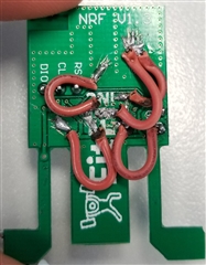
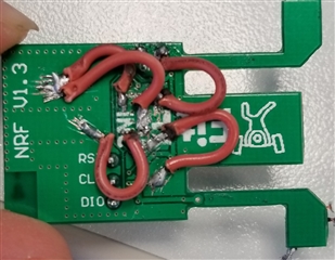
I have designed nrf52832 customized board with tace antenna antenna and every pin of the controller is connected to the male headers present on both side of the boards. I havent used lpkf , so I changed the sdkconfig.h file to use internal RC but it wasnt working. By mistake , the P0.07 pin gets connected to Vcc and the led start blinking i.e. the bluetooth is advertising. Now ble is working fine but everytime I have to connect this P0.07 with 3.3v or also with little variation on that pin (like when I Just touch that pin with my fingers). I want to kmow that P0.07 is just an I/o pin , so why this behaviour? DOes it mean there is problem in my layout design.

There is no problem in the code as I'm using the standard code of ble of nrf52 dk by changing the sdkconfig.h as we dont have lpkf

Parents
  • Ohk I will post you the schematic and layout soon. But a quick question,as you have said, the capacitor size matters!!.

     I have used various 0201 capacitors instead of 0402 and 0603 but with the same specs given in nrf datasheet. Does that honna make any difference?

  • I should have said “capacitance value”. For the logic portion of the chip, the physical size is not too important. But since the SRF ( series (or self) resonant frequency ) is strongly correlated with the value, it is best to use a combination of large and small value caps as they do in the reference design. 

    On the RF the physical size of the cap influences the size of the pads and microstrips that should be used. This is more a method of controlling parasitic reactances on RF.

    Our own designs make use of 0201 parts for much of the logic and all of the RF. Only bulk storage capacitance is made up of 0402 and 0805s. We utilize 0805s since our main product is a coin cell powered device. Thus we need a lot of local capacitance.

    happy to review your design and provide feedback.

  • Not sure why your cad app didn't pick up the mistake.  But the connecting dot at pin 49 is suspicious.  It's possible it didn't think the ground slug on the nRF was part of ground.

  • ohhh.. I see.. Thats a big mistake. The ground Pad of the nrf is connected through gnd just through cap C8 and C7 which is not sufficient, Thanku so much for pointing this out. I think this is the only problem.I will try to do the connections manually and for my new design checking that I will make, can I send the layout on your email id ([email protected]) or should I post it here ?

    and more thing. You said this

    "The way you have done the layout on your board none of the local capacitances are really doing anything since they are not connect to the same ground as the nRF."'

    because the nrf pad gnd is not at all connected to the gnd, its just through the c8 and c7. right?

  • You can send your updated layout for review to my email if you wish. 

    Yes the local capacitors are not doing anything because the length of board surface the current must flow is so long that there is significant resistive losses and parasitic inductance. Also since the ground currents for the entire nRF pass through that same narrow connection they talk to each other ( or couple). These are often called ground loops and are a large source of noise in a device.

  • FormerMember
    0 FormerMember in reply to Navdeep

    (It is also possible to upload layout for review in private case here on devzone.)

    Thanks @AmbystomaLabs for such good and detailed answers!

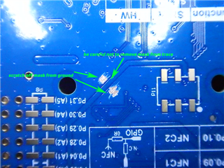
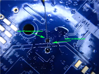
  • I have done 2 connections with ground to the nrf pad (49) by scratching off the solder mask one connection through the cap c7 and c8 via , but still the problem persists. I think this is the only issue. SO should I go for new layout ? I will mail you the new design for the review.

Reply Children
Related