This post is older than 2 years and might not be relevant anymore
More Info: Consider searching for newer posts

How to transmit and receive beacons using nRF51 DK?

I need to transmit and receive beacons using nRF51 DK. I saw a few examples in the SDK ble_beacons where we use the app, but I need code to transmit and receive both using the nRF51 Development kit. Also, can you give me steps for setting up GCC for the nRF51DK, how do I setup that IDE for using it with the DK, if there are any youtube videos for setting up the GCC for the nRF51DK please send me the links. Also while receiving the beacons, I need the RSSI value at the receiver and how do I get that value?  Thank you so much for your help. Also, I need to know while transmitting from one nRF51DK to another is it necessary to pair the boards etc?

Parents
  • Hi,

    I need code to transmit and receive both using the nRF51 Development kit.
    First of all I think there is a misunderstanding regarding beacons. A BLE beacon is per definition not receiving anything. It is just mindlessly broadcasting a handful of bytes. If you want bidirectional communication between two nRF51 devices I suggest that you start out with the UART/Serial Port Emulation over BLE and Nordic UART Service Client examples. 

    can you give me steps for setting up GCC for the nRF51DK
    Unfortunately, we only have this relatively old tutorial: Development with GCC and Eclipse

    I need the RSSI value at the receiver and how do I get that value? 
    Please have a look at these APIs: sd_ble_gap_rssi_start(), sd_ble_gap_rssi_stop(), and sd_ble_gap_rssi_get().

    I need to know while transmitting from one nRF51DK to another is it necessary to pair the boards etc?
    It depends. But I suspect that you might be confusing BLE pairing and bonding.


  • Hello MartinBL,

    First of all thank you so much for your help. I tried to execute the Nordic UART service Client on two dev boards, I programmed both the soft device and the hex file into both the boards ( I am not sure if I had to program both the boards with the same code but that's what I did) and both of those boards were advertising and not able to connect to each other. If you have any solution for that please let me know.

    Also, I executed the radio transmitter and receiver example in the SDK, Its path is <InstallFolder>\examples\peripheral\radio\receiver and <InstallFolder>\examples\peripheral\radio\transmitter. My question is is there some sort of API I can use to get the RSSI or the signal strength on the receiver side because I think the API's that you mentioned above are for BLE and this application does not use BLE. So if you had something that would be really helpful for my project.

  • Hello,

    Thank You for all your help, I got the rssi working.

    Can you tell me how do I program the chips nrf51822 chips, right now I am working with the Development Kits but eventually I want to work with the chips so I need to know how to program them? Also, right now in the radio transmitter code, it transmits every time a button is pressed, I want to transmit a packet every second or every two seconds, can you tell what changes need to be done for that in the transmitter code.

    Thank You.

  • Q1) The nRF5 series uses the Serial Wire Debugging (SWD) protocol for programming. To program a prototype you typically need access to the SWDIO and SWDCLK signals as well as ground and Vdd. Most of Nordic's development kits come with an on-board debugger and you can use the the Debug OUT header on the kit to program external prototypes. 

    Q2) The easiest way is to use a software delay in a while loop like this:

    while(1)
    {
        nrf_delay_ms(1000);
        // Transmit your data here.
    }

    The slightly more complex, but much more power efficient way is to use a timer and configure an interrupt to trigger your transmissions at the specified intervals. Please refer to the "peripheral/timer" examples in the SDKs.

  • I am creating a PCB layout for my application, I connected my SWDIO and SWDCLK to a 2 pin connector so that I can program it using my NRF51DK, the VDD will be supplied by the battery (3V), is that correct or do I need more than 2 pins to program the chip?

  • You need common ground, SWDIO, SWDCLK, and Vdd. Vdd should be connected to the VTG pin on the DK so that the DK can detect the presence of an external PCB. There are a lot of threads here on devzone that discuss how to program external PCBs so if you have issues I suggest you skim through them. 

  • Hello MartinBL,

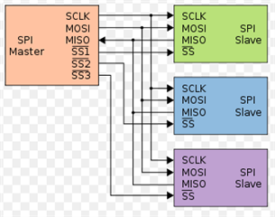
    Thank You for all your help. I had a doubt regarding SPI's, so in my application, one nRF51822 chip is connected to four others nRF51822 using SPI, I was wondering whether the SCK, MISO, and MOSI pins can be shared between all the chips? From the Master chip the SCK, MISO, and MOSI go into all the other four chips or do I have to define separate SCK, MISO and MOSI pins for all of them?

    Thank you,

    Have a good day.

Reply
  • Hello MartinBL,

    Thank You for all your help. I had a doubt regarding SPI's, so in my application, one nRF51822 chip is connected to four others nRF51822 using SPI, I was wondering whether the SCK, MISO, and MOSI pins can be shared between all the chips? From the Master chip the SCK, MISO, and MOSI go into all the other four chips or do I have to define separate SCK, MISO and MOSI pins for all of them?

    Thank you,

    Have a good day.

Children
Related