Hello guys,
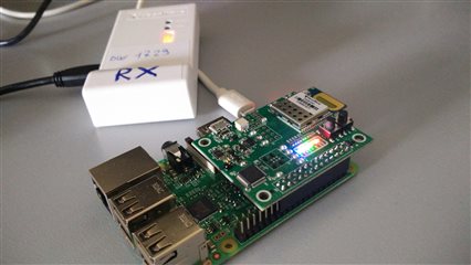
I'm having problems with communication between a dwm1001 module (from Decawave) which is a nrf52832 board, and my Raspberry 3 Pi model B.
I have connected the nrf52832 board to the Raspberry using the 26-pins header

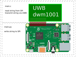
My goal is to send/write a message from Raspberry to dwm1001 module. Inside the Raspberry I wrote a simple python script in order to write to the SPI port:
import spidev
import time
spi = spidev.SpiDev()
spi.open(0,0)
spi.mode = 0b00
while True:
    data = [ 0xcc ]
    resp = spi.xfer(data)
    print resp
    time.sleep(1)
So, now I don't know if this *is* the correct way, but I have found this in internet.
In the other side, that is the nrf52832 board, I currently implemented the C code firmware so read from SPI.
#define SPI_INSTANCE  0 /**< SPI instance index. */
static const nrf_drv_spi_t spi = NRF_DRV_SPI_INSTANCE(SPI_INSTANCE);  /**< SPI instance. */
static volatile bool spi_xfer_done;  /**< Flag used to indicate that SPI instance completed the transfer. */

#define TEST_STRING "Nordic"
static uint8_t       m_tx_buf[] = TEST_STRING;           /**< TX buffer. */
static uint8_t       m_rx_buf[sizeof(TEST_STRING) + 1];    /**< RX buffer. */
static const uint8_t m_length = sizeof(m_tx_buf);        /**< Transfer length. */

/**
 * @brief SPI user event handler.
 * @param event
 */
void spi_event_handler(nrf_drv_spi_evt_t const * p_event,
                       void *                    p_context)
{
    spi_xfer_done = true;
    NRF_LOG_INFO("Transfer completed.");
    if (m_rx_buf[0] != 0)
    {
        NRF_LOG_INFO(" Received:");
        NRF_LOG_HEXDUMP_INFO(m_rx_buf, strlen((const char *)m_rx_buf));
    }
}

int main(void)
{
    bsp_board_leds_init();

    NRF_LOG_INIT(NULL);
    NRF_LOG_DEFAULT_BACKENDS_INIT();

    NRF_LOG_INFO("SPI example.");

    /*
    FROM Decawave

    #define SPIS_MISO_PIN   28  // SPI MISO signal.
    #define SPIS_CSN_PIN    12  // SPI CSN signal.
    #define SPIS_MOSI_PIN   25  // SPI MOSI signal.
    #define SPIS_SCK_PIN    29  // SPI SCK signal.

    #define SPIM0_SCK_PIN   2   // SPI clock GPIO pin number.
    #define SPIM0_MOSI_PIN  3   // SPI Master Out Slave In GPIO pin number.
    #define SPIM0_MISO_PIN  4   // SPI Master In Slave Out GPIO pin number.
    #define SPIM0_SS_PIN    5   // SPI Slave Select GPIO pin number.

    #define SPIM1_SCK_PIN   16  // DWM1001 SPIM1 sck connected to DW1000
    #define SPIM1_MOSI_PIN  20  // DWM1001 SPIM1 mosi connected to DW1000
    #define SPIM1_MISO_PIN  18  // DWM1001 SPIM1 miso connected to DW1000
    #define SPIM1_IRQ_PRIORITY APP_IRQ_PRIORITY_LOW //
    #define SPIM1_SS_PIN    XX  //  Not used with DMW1001

    #define SPIM2_SCK_PIN   12  // SPI clock GPIO pin number.
    #define SPIM2_MOSI_PIN  13  // SPI Master Out Slave In GPIO pin number.
    #define SPIM2_MISO_PIN  14  // SPI Master In Slave Out GPIO pin number.
    #define SPIM2_SS_PIN    15  // SPI Slave Select GPIO pin number.
    */

    nrf_drv_spi_config_t spi_config; //= NRF_DRV_SPI_DEFAULT_CONFIG;
    spi_config.ss_pin    = NRF_DRV_SPI_PIN_NOT_USED; //SPI_SS_PIN;
    spi_config.miso_pin	= 18; //SPI_MISO_PIN;
    spi_config.mosi_pin	= 20; //SPI_MOSI_PIN;
    spi_config.sck_pin  = 16; //SPI_SCK_PIN;
    spi_config.orc		= 0xFF;
    spi_config.frequency = NRF_DRV_SPI_FREQ_125K;
    spi_config.mode      = NRF_DRV_SPI_MODE_1;
    spi_config.bit_order = NRF_DRV_SPI_BIT_ORDER_MSB_FIRST;
    nrf_drv_spi_init(&spi, &spi_config, spi_event_handler, NULL);

    while (1)
    {
        // Reset rx buffer and transfer done flag
        memset(m_rx_buf, 0, m_length);
        spi_xfer_done = false;


        ret_code_t ret = nrf_drv_spi_transfer(&spi, m_tx_buf, m_length, m_rx_buf, m_length);
        NRF_LOG_INFO(" Code: %d:", ret);

        while (!spi_xfer_done)
        {
            __WFE();
        }

        NRF_LOG_FLUSH();

        bsp_board_led_invert(BSP_BOARD_LED_0);
        nrf_delay_ms(200);
    }
}
But I cannot read anything. In practice I checked that the flow passes through the spi_event_handler function, but my goal is not reached.
Finally, my very final goal is the following:

Thanks in advance.


