
hi!
I use the reference design of nrf52832_ciaa.IntLib ,but it didn't work
I use the internal-LDO ,but i measure the voltage of DEC4, it's 2.5V(not 1.3V), the VDD is 2.9V
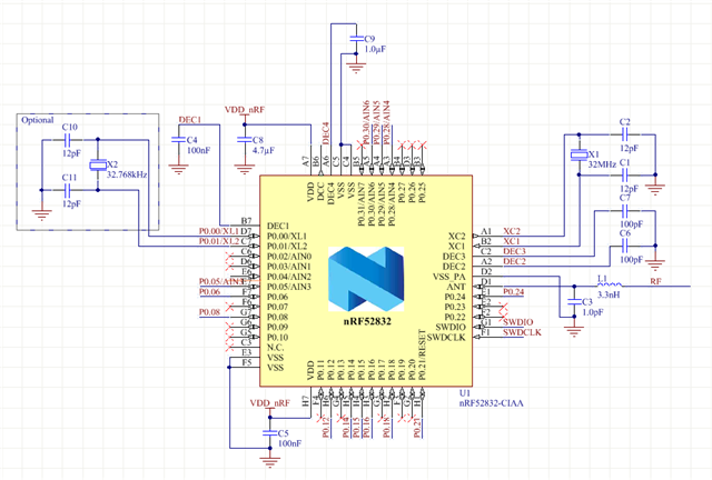
which reason can cause the DEC4 to 2.5V?
hi!
I use the reference design of nrf52832_ciaa.IntLib ,but it didn't work
I use the internal-LDO ,but i measure the voltage of DEC4, it's 2.5V(not 1.3V), the VDD is 2.9V
which reason can cause the DEC4 to 2.5V?


